This thread has been locked.

If you have a related question, please click the "Ask a related question" button in the top right corner. The newly created question will be automatically linked to this question.

TLV9062: TLV9062 Input resistor question

Part Number: TLV9062

Tool/software:

Hi Team,

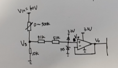
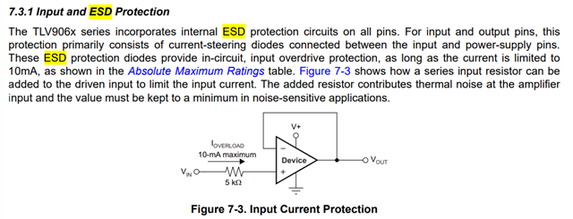
For TLV9062 it shows the below typical application, could you please help to check how customer determined the largest input resistor they could add at the device in+ pin? The datasheet mention use a minimum resistor at a noise sensitive system, but it doesn't mention the up limitation for this resistor. Could you possible help to double check? Thanks a lot for your help.

Best regards

Jie

  • Jie,

    As large as you like considering input does have a small amount of input bias current (more at high temperature) and a couple picofarad of capacitance.

  • Hi Ron,

    Thanks a lot for your feedback. 

    If customer use a larger resistor, then, if the thermal noise would become bigger? Customer want to know if consider thermal noise, then, how could customer determine the larger resistor limitation? For the Vin+, customer would give a 4.18V.

    Thanks a lot for your help to check again.

    Best regards

    Jie

  • Jessica,

    The resistor noise adds to input signal. 

    The formula for calculating thermal noise voltage in a resistor is V = √(4 * k * T * R * Δf), where: V is the RMS noise voltage in volts, Boltzmann's constant (approximately 1.38 x 10^-23 J/K), T is the temperature in Kelvin, R is the resistance in ohms, and Δf is the bandwidth in Hertz.

    Assuming 1% noise of 0.0418V at 300 Kelvin, F = 10MHz , limits R to 10 G

  • Hi Ron,

    Thanks a lot for your support before.

    One more follow up question comes from customer is if customer give a supply voltage of 3.3V, and with V+ pin =4.18V, then, if our device could support it? Any risk here if customer use our device like that? Thanks a lot for your support to check again.

    Best regards

    Jie

  • Jessica,

    No IN+ cant be 4.18V with supply at 3.3V.  That is why the image in original post has a resistor. 

    Can they supply a schematic, input signals, and a description of what the circuit should do. 

  • Hi Ron,

    Below shows customer design, their application is want the output voltage between 0V~3.3V, even with input voltage of 0~4.1V; It will be fine for customer application when the input above 3.3V, the output can keep 3.3V.

    From datasheet, we think customer could use under that kind of condition as long as we limit the input current less than 10mA, correct? 

    Best regards

    Jie

  • Jie,

    output voltage between 0V~3.3V, even with input voltage of 0~4.1V; It will be fine for customer application when the input above 3.3V, the output can keep 3.3V.

    Yes.