This thread has been locked.

If you have a related question, please click the "Ask a related question" button in the top right corner. The newly created question will be automatically linked to this question.

THS3470: Evaluation board dies unexpected

Part Number: THS3470

Tool/software:

We have evaluated the THS3470 on the evaluation board THS3470EVM. 

Setup:
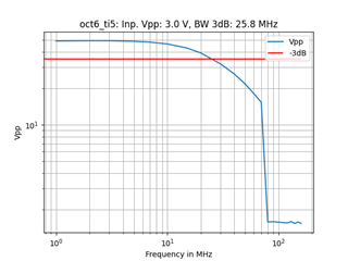
OPV was powered with +-30, current limited to 2A. Output voltage was 50Vpp. Output was connect with 1m RG58 cable to Lecroy Oscilloscope with high impedance (1MOhm). 
Amplification 5 as delivered. All switches in middle position, as delivered. 

Input frequency was programmatically increased from 1 MHz to 150 MHz. Oscilloscope measured Vpp.

Fan was running. 

In the middle of the measurement (frequency was increased programmatically) the OPV dies. Supply voltage drops to 1.5V at 2A for both +30V and -30V.
Here are the recorded measurement results:

I would expect that the IC was driven under normal operation conditions and I wonder why it was killed. 

Are there any comments?

Regards, Guenter

  • Hey Günter,

    Thanks for the question. Before I jump into the details, I just wanted to let you know that this is pre-release silicon (RevA) of the THS3470. We've since made some improvements to the die, in a couple of ways, and the final silicon will not exhibit some of the "quirks" present in the RevA.

    Some notes for you below:

    1. I would suggest you limit the output current, for now, to 1A using the ISRC_LIMIT and ISNK_LIMIT pins with their respective resistors. This function is outlined in section 6.3.1 of the preliminary datasheet. We do suggest that customers keep the DC current limited below 1.5A on the front page of the datasheet.
    2. I would also suggest you leave the 2k-ohm feedback resistor if you are planning to use the device at 60V supply. This resistance is here to limit feedback current & bandwidth to help customers manage thermals on the device.
    3. I would suggest you keep your sinusoid signals, for now, within the unity gain bandwidth of the device. Signals exceeding the bandwidth of the device can cause and inordinate amount of shoot-through current on the RevA version of the device. This was fixed in our RevB silicon, which we are still evaluating before RTM.
    4. I would suggest you monitor the DIE_TEMP pin to see what junction temperature the device is reaching
    5. I would suggest you connect the OVTEMP_FLAG pin to the P0 and P1 pins to trigger a rough thermal shutdown on the device.

    1m of coax should be 100pF of capload. The device died at around 70MHz at 3VPP, which is about 1300V/us. This means your peak current for the device is ~130mA, which shouldn't be an issue for the part.

    Ultimately, you are likely taking the device junction temperature beyond the absolute maximum specifications in Table 5.1 of 150C. I think it's probably because of the elevated shoot-through current on the RevA silicon. Can you re-run the experiment for me and stop at the -3dB cutoff? Can you record the die temperature from the DIE_TEMP and monitor the quiescent current to the device?

    If we identify the root cause as the shoot-through current I can connect with you offline and send you some RevB silicon to evaluate.

    Hope this helps,
    -Mitch

  • Hello Mitchell,

    thank you for the comprehensive answer. 
    Can you tell me your time schedule for the first samples of Rev. B and availability in bulk. I'm still interested to evaluate it for the project. 

    In the TI store the OPV is not available. Is there an option to get currently a replacement of the OPV?

    Thank you 
    Guenter

  • Hey Guenter,


    I reached out to you via email so we could discuss getting you some preliminary RevB samples. We can discuss timelines for release there as well!

    Thanks,

    -Mitch