This thread has been locked.

If you have a related question, please click the "Ask a related question" button in the top right corner. The newly created question will be automatically linked to this question.

AMC3301: Trouble simulating in pspice

Part Number: AMC3301

Tool/software:

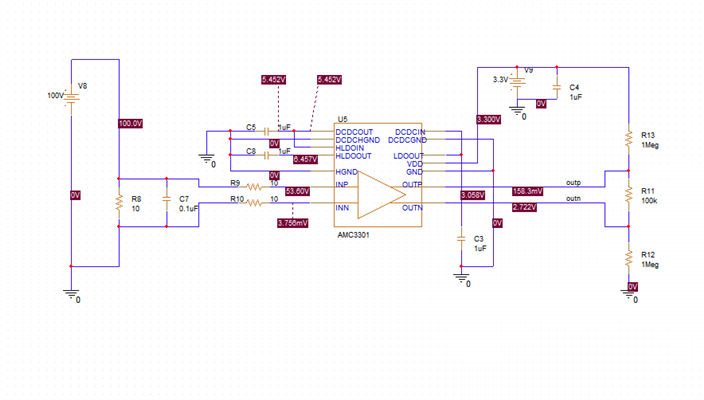
I'm struggling a bit to simulate the AMC3301. I want to use it to measure current on the high side of my circuit, and on paper it looks like it should work but I'm struggling in ti-pspice.  If I simulate for 1000us I always get the output shown regardless of what value the shunt at R8 is.  If I try to extend the simulation to say 1ms, then it falls apart with convergence issues. What did I miss?

Also in the real design that shunt will be driven by an hbridge so the polarity will swap. I'm hoping that's okay.

Thank you

  • Hi Eric,

    What is the convergence failure you see with 1ms? It's interesting you get the same output no matter what R8 is. A first suggestion is it does not look like you are properly dividing your voltage before the input of the device, this is a 250mV input device. It also looks like you are using this current sensing device for voltage sensing. This is okay, but we would generally suggest some schematic changes if doing as described in this app note:

    Isolated Voltage-Measurement Circuit With ±250-mV Input and Differential Output (Rev. A)

    Please let me know if following these guidelines help and if there are any more questions, thank you.

    Best regards,

    Eva

  • Not sure if this is enough detail but in the logs I see this:

    Reducing minimum delta to make the circuit converge.

    ERROR(ORPSIM-15138): Convergence problem in Transient Analysis at Time =  291.0E-21.
             Time step =  291.0E-21, minimum allowable step size =  1.000E-18

    I'm trying to use it as a current monitor for less than 20mA. I thought I understood that its input can just float on the high voltage side and measure the shunt?  Perhaps I don't know exactly what I'm doing with this part :)

    Thank you

  • Hi Eric,

    Okay thank you for clarifying. Using this device to sense 20mA makes more sense, it just wasn't clear at first from the schematic. It looks like at the input of the device there is ~50V. I think changing your source to be input current in the diagram and ensuring the input of the device is within the input voltage range of the AMC3301 (+/-250mV) will be a next step. Please let me know if you can make these adjustments and if you still see these errors. 

    Best regards,

    Eva