This thread has been locked.

If you have a related question, please click the "Ask a related question" button in the top right corner. The newly created question will be automatically linked to this question.

INA826: Fully differential input handling with INA826

Part Number: INA826
Other Parts Discussed in Thread: TINA-TI

Tool/software:

Subject: Help with AFE Design and Simulation for 0–42 mV Input Signal Using INA826

Hi TI Team,

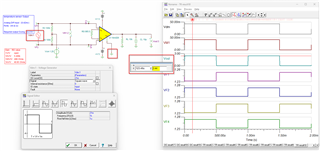
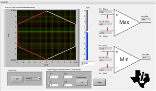
I'm currently working on designing an Analog Front-End (AFE) to interface with a low-level analog input signal ranging from 0 to 42 mV(Temperature sensor differential output (Uhi andUz)), and I need the output to swing from 0 to 2.5 V.

I'm trying to simulate this using TINA-TI based on the INA826 reference simulation file available on your website. However, I'm unable to achieve the desired 0–2.5 V output range corresponding to the 0–42 mV input in the simulation.

Could you please help me resolve this issue in the simulation? Additionally, I’d like to confirm if the INA826 is the appropriate choice for accurately handling this low-level input signal, or if you would recommend a better-suited alternative.

Looking forward to your guidance and support.

Thanks & Regards,
Manikandan V

  • Hi Manikandan, 

    Could you share the TINA simulation you were trying to use to test your conditions? Did you modify the supply voltage, reference voltage, or gain setting? What output voltage were you seeing instead? 

    Regards,
    Ashley

  • Hi Ashley,

    Thank you for your response.

    I've tried several configurations, but unfortunately, I haven't been able to get the expected results.

    I'm sharing the TINA simulation file I used for testing:
    File: sbom471 (1)--tuning-TI.TSC

    Note: I'm relatively new to AFE designs, especially those involving small input signals.

    sbom471 (1)--tuning-TI.TSC

    Best regards,
    Manikandan

  • Hi Manikandan, 

    I made a couple of adjustments to your schematic as listed below and re-uploaded the TINA simulation. Please let me know if there are other adjustments you need to fit your application better. 

    • Reference voltage was shifted to GND. The reference voltage will shift your output signal, so if you need an output of 0-2.5V, the reference voltage has to be 0V. 
    • Input signal range was adjusted to match the conditions you listed. I changed to a square wave to better visualize, but this can be changed back to any waveform shape. The input conditions were stated to be 0-42mV. The input signal source needs to be offset 21mV and the amplitude 21mV in order for the simulation to show a waveform from 0-42mV. 
    • The output now shows an output range from 0 to 2.44V. 

    sbom471 (1)--tuning-TI-edits.TSC

    Please note that depending on your input common-mode range, reference voltage, and supply voltage, the output swing limit will also change. This behavior is not shown in the TINA model and can be calculated via the Analog Engineer's Calculator. Based on your current conditions shown in the schematic, the output range of 0-2.5V should work with the INA826. 

    Please let me know if you have further questions.
    Thank you!

    Regards,
    Ashley