This thread has been locked.

If you have a related question, please click the "Ask a related question" button in the top right corner. The newly created question will be automatically linked to this question.

INA180: Simulation problems when not Global-ground-referenced

Part Number: INA180
Other Parts Discussed in Thread: INA185

Tool/software:

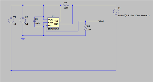
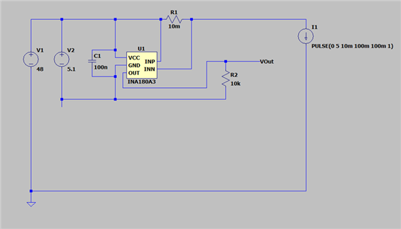
I'm having problems simulating INA180A3 when not directly GND referenced. It seems like the Spice model references Global simulation ground, rather than local VCC-GND pins.

We intend to use this on a 48V rail, with a local -5.1V (42.9V from "real" GND) supply for the current monitor GND.  This drives a comparator to generate a trip signal, which is referenced to "real" ground through other circuitry.

If I make the GND pin of the INA180A3 simulation GND, the simulation works, but it's not helpful for anlysing the rest of the circuit ("real" ground effectively becomes a -42.9V rail), and simulation runs millions of times slower.

Simulating the circuit as intended, the INA180A3 behaves the same as if it was driven with VCC above spec (verified by simulating just the current monitor in isolation).

Is there some internal clamp in the INA180A3 Spice Model that re-references model-local voltages to Global simulation GND?  Or something that references absolute simulation voltages rather than local VCC-GND pins?

Thanks,
Gordon

  • Hi Gordon,

    The INA180 isn't meant to work at Vcm beyond 26V, so there are protective internal clamps that will render the device unfunctional beyond 26V. 

    Best,
    Mallika Senthil

  • Hi Mallika,
    Thanks for your reply; unfortunately it doesn't address the question. 

    It's not about the voltage the device sees, it's about why the simulation model doesn't work when not ground referenced.  In the two screenshots below, the circuit is identical.  The INA180A3 has VS = 5.1V (VCC-GND pins), and VCM = 5.1V (i.e. VCM = VCC).  The circuits are identical, the only difference is which net is Simulation Ground.

    When Simulation Ground is connected to the INA180A3, it behaves as expected.  When Simulation Ground is connected elsewhere, the simulation doesn't work.  It's as if the INA180A3 simulation model internally references Global Simulation GND instead of referencing the GND pin of the device.

    This works:

    Why doesn't this work?

    Regards,
    Gordon

  • Gordon,

    Thanks for the question and using the E2E forum.

    Due to the U.S. holiday on July 4, we are currently out of the office. Someone will reply when we return on Monday, July 7.

    Thank you for your patience.

  • Hi Gordon,

    Thank you for the clarification, practically, the second schematic should work but I believe certain simulation restrictions are preventing it from working. I'd recommend adding another ground to V2 and labelling it GND2 to differentiate it from V1 ground. If that doesn't work, try adding a large resistor (1M) from V2 (-) to V1 ground.

    Best,
    Mallika Senthil

  • Hi Mallika,

    Thanks for the suggestions....unfortunately neither work on this sim.  I tried renaming the "GND" net in the Spice model as VSS, but that didn't work either.  I'll have a look for any absolute / Global voltage comparisons when I have more time.....a bit frustrating, but a good opportunity to learn the Spice language properly.

    Best regards,
    Gordon

  • Hi Gordon,

    I'll try simulating this on my end and get back to you soon.

    Best,
    Mallika Senthil

  • Hi Gordon,

    The INA180 model may be restricted by the global ground link you mentioned above. In the meantime, please try simulating with the INA185 instead, it shouldn't have the same restrictions.

    Best,
    Mallika Senthil

  • Hi Mallika,

    This works perfectly, thank you very much.

    Best regards,
    Gordon