This thread has been locked.

If you have a related question, please click the "Ask a related question" button in the top right corner. The newly created question will be automatically linked to this question.

TLV6001: Error simulating the model using Single Power Supply

Part Number: TLV6001
Other Parts Discussed in Thread: TINA-TI

Tool/software:

I am using the following specific part: TLV6001IDCKT.

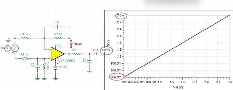
I am trying to simulate a voltage sensing circuit using the sboma17d simulation file. I want to use this component with a single power supply configuration +3.3V, GND. 

When I run this model using Altium Simulator, I get a FAILED TO CALCUALTE DC POINT ERROR. But when I add a -5V power supply instead of GND. It does simulate, however I do not get the desired output. I have attached an image of the circuit. 

How can I simulate using a single power supply?

VCMADC is connected to GND.

  • You run into convergence issue related to supply voltage BUT you do not show the component values (gain), input voltage and what you get adding negative 5V supply? 

    Please make sure that the input differential signal has correct polarity:  VOUTP > VOUTN

    Even though the TLV6001 input common-mode voltage range is literally from rail-to-rail, no op amp's output can ever completely reach its rail and in the case of TLV6001 2k load is specified within 300mV of either rail (see AOL conditions below).  Thus, under Vin_diff = 0 output cannot reach theoretical ground and may run into convergence issue.

    Tina-TI will converge under such non-linear conditions (see below) BUT other simulators like ALTIUM may not (you should ask Altium support team for assistance).

    Below I have attached Tina-TI simulation file.  You may download a free copy of the simulator by clicking on following link: https://www.ti.com/tool/TINA-TI

    TLV6001 diff amp.TSC

  • Here are the values I am getting with -5V supply. I did my theoretical calculations based on just a 3v3 power supply and it showed that the output at pin 4 should be roughly 2.35V but I am not getting that.

  • With Vout_P above VOUT_N input, the output will be a positive voltage and thus there is no need for negative rail.  Having said that, I'm not sure how did you determine that the output would be 2.35V since the gain of the circuit is determined by the ratio of R3/R1; G=1.5

    Vout = Vref + (Vin_diff*Gain)

    Therefore, the output of 772.8mV you simulate is correct with 1.8mV error caused by Vos - see below.

    Please be aware that he AC bandwidth will be limited by the low-pass filter formed by R1||C1 - see below.

  • Hi, I have figured out the problem. There was a issue with the circuit before this part and It was not outputting the required input range for this part of the circuit.

    Thank you for the help. 

  • Glad I could assist you.  Good luck!