This thread has been locked.

If you have a related question, please click the "Ask a related question" button in the top right corner. The newly created question will be automatically linked to this question.

PGA308: Assistance with PGA308 Configuration and Operation Using Arduino

Part Number: PGA308
Other Parts Discussed in Thread: DAC8555,

Tool/software: Arduino IDE

Hello,

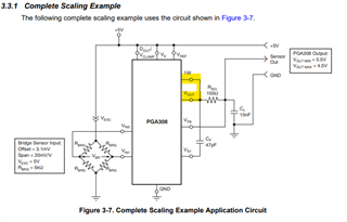
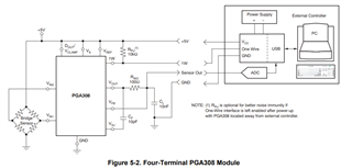
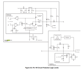
I am a new user of this type of component, and so I used the guide provided in the datasheet, "PGA308 User's Guide (SBOU069)," to base my understanding of the system. To set the context, I am using an Arduino Mega to test the component initially, with a DAC8555 to simulate the two sensor outputs, Vin1 and Vin2. For the Vout, Vf, Vsj, Vs, and Vref pins, I used a setup similar to the one shown in "Figure 3-7," with the Dout/Vclamp pin left floating and the 1W pin connected to the UART port of my Arduino (Rx and Tx).

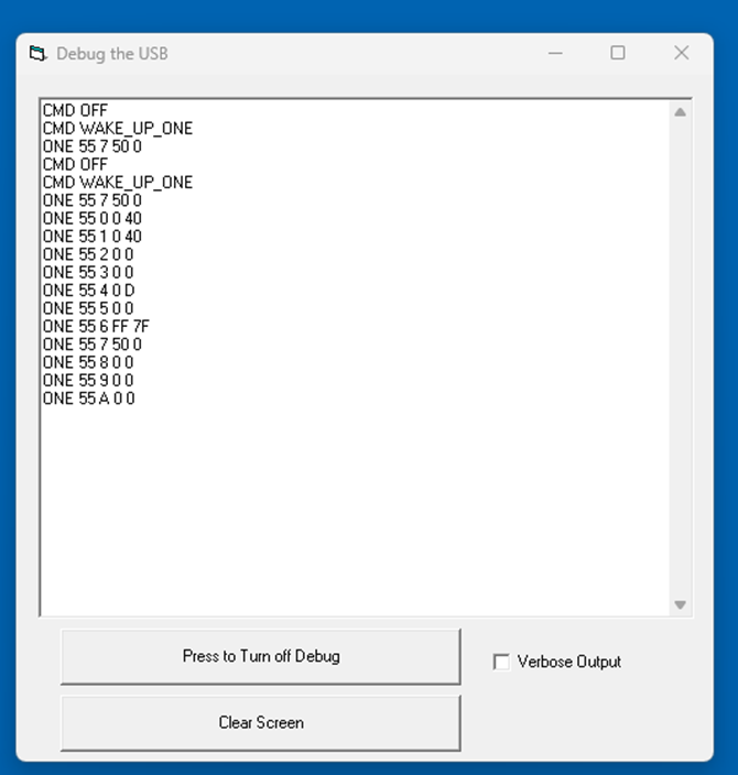
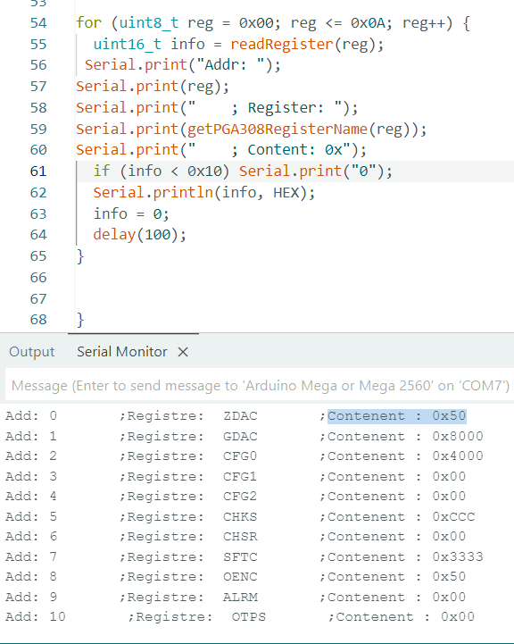
For the software part, I started by putting the component in "Software Lock Mode." Then, I began writing and configuring the ZDAC register to observe a change in the output voltage "VOUT" using the frame explained in "Figure 4-2," with the UART baud rate set to 4800 bits/second. However, the parameter still does not change. I also tried reading from the same pin using the command from "Figure 4-2," but I obtained a voltage of 3V that only changes when modifying the two input voltages.

I was also able to examine the input and output signals with an oscilloscope and observed that the frame was correct. However, when reading the register data, I noticed that the 16 bits of the data had the same shape as the sent data, except that the low state did not fully drop to 0.

Thank you in advance for your help.

  • Hello Ferhat, 

    Welcome to e2e Slight smile One of the great things about the forum is the reusability of previous forum posts. 

    In Figure 3-7 of the User's Guide, the PGA308 is configured in three-wire mode, meaning the 1W is connected to VOUT:

    There is an existing e2e with a similar issue, see here: (+) PGA308EVM: Software Lock Mode - VOUT not enabling after programming the registers - Amplifiers forum - Amplifiers - TI E2E support forums

    Mostly focused on this portion of the response: 

    For the purposes of evaluating the device with your arduino, I recommend separating the VOUT and 1W and implementing the following code with your UART: 

    Most engineers have a much easier time by ordering the PGA308EVM and using the GUI to first evaluate this device, I recommend this. 

    All the best,
    Carolina

  • First of all, I would like to sincerely thank you for taking the time to respond to my inquiry.

    I am currently working with the PGA308 without the PGA308EVM, and I would like to kindly ask whether it is possible to use the configuration you previously shared in combination with my Arduino-based program to evaluate the component.

    Regarding the hardware setup, would simply connecting the 1W line to the TX pin of the Arduino board, along with a pull-up resistor, be sufficient for proper communication with the PGA308?

    Thank you once again for your support and guidance.

    All the best,

  • Hello Ferhart, 

    I am not sure, I haven't used Arduino's UART in the past, here is their page: Universal Asynchronous Receiver-Transmitter (UART) | Arduino Documentation

    I recommend to setup the PGA308 in the following configuration: 

    I recommend having an extremely small wire between 1W and your UART communication, if not the following will also need to be implemented: 

    If you are not using the EVM, does this mean you have a custom board? Can you share the schematic? 

    All the best,
    Carolina

  • Hello Carolina,


    I was able to establish the connection properly, and I can now read both the default registers and those after configuration. So the communication with the registers seems to be working fine.

    About the setup you suggested earlier — I had a question regarding the Dout/Vclamp pin on the PGA308. From what I understand, this pin needs to be configured either in Vclamp mode or Dout mode. Please correct me if I’m wrong, but in Dout mode, the pin acts as a digital output that can be set to a high or low logic level. In Vclamp mode, it’s used to limit the output voltage by connecting a specific voltage that defines the clamp level of the component.

    If I got it right, it's the Vclamp mode that’s being used in the setup you recommended.
    Thanks a lot in advance for your help!

  • And I also have a small issue: when I start reading, it begins with the value I programmed in the SFTC register — even if I request to read register 0x00, which is the ZDAC.

  • Hello Ferhat, 

    Your understanding of VClamp and DOUT is correct. 

    I am not sure what you mean by this, could you share more details:

    when I start reading, it begins with the value I programmed in the SFTC register — even if I request to read register 0x00, which is the ZDAC.

    All the best,
    Carolina

  • Hello Carolina,

    I just wanted to mention that when I start reading the content of the registers using the function I referred to yesterday, it consistently begins by reading the SFTC register with the value 0x50, before proceeding to read the other registers.

    Thank you in advance for your help!