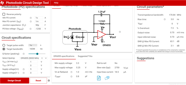
This thread has been locked.

If you have a related question, please click the "Ask a related question" button in the top right corner. The newly created question will be automatically linked to this question.

OPA855-Q1: PMT pulse detection circuit

Part Number: OPA855-Q1

Tool/software:

Help with Circuit Design for H6520 PMT – Single/Few-Photon Pulse Detection

Hello E2E Experts,

Good day.

I'm designing a pulse-counting circuit using the Hamamatsu H6520 PMT to detect single to few-photon events from a chemical reaction (triggered via chemiluminescence). The datasheet for this PMT is limited, and I would like help in designing the circuit to capture the output pulses with good timing accuracy and very less noise.

Specifications
Assembly Size Dia                                                              23.5 mm
Built-in PMT Type No.                                                         R1166
Photocathode Area Shape                                                  Round
Photocathode Area Size Dia.                                              15 mm
Wavelength (Short)                                                              300 nm
Wavelength (Long)                                                               650 nm
Wavelength (Peak)                                                              420 nm
Spectral Response Curve Code                                          400K
Photocathode Material                                                         Bialkali
Window Material                                                                  Borosilicate glass
Dynode Structure                                                                 Linear-focused
Dynode Stages                                                                    10
[Max. Rating] Anode to Cathode Voltage                            -1250 V
[Max. Rating] Average Anode Current                                  0.33 mA
Anode to Cathode Supply Voltage                                      -1000 V
[Cathode] Luminous Sensitivity Typ.                                    110 μA/lm
[Cathode] Blue Sensitivity Index (CS 5-58) Typ.                  10.5
[Anode] Luminous Sensitivity Typ.                                       110 A/lm
[Anode] Gain Typ.                                                                1.0 x 10⁶
[Anode] Dark Current (after 30min.) Typ.                             1 nA
[Anode] Dark Current (after 30min.) Max.                            5 nA
[Time Response] Rise Time Typ.                                          2.5 ns
[Time Response] Transit Time Typ.                                      27 ns
[Time Response] Transit Time Spread Typ.                          2.8 ns
[Anode] Pulse Linearity (2% deviation)                                  == 4 mA
[Anode] Pulse Linearity (5% deviation)                                 7 mA
Output Type Current pulse (terminated with 50 Ω)

PMT link: www.hamamatsu.com/.../H6520.html

Application Details:
Need to detect single to few-photon events.

PMT output: fast, small current pulses (~μA to mA).

50 Ω termination → pulse voltages in tens of mV.

Goal: high SNR + wide bandwidth to preserve pulse shape.

  • Hello Jinen,

      Thank you for reaching out. If you are looking to match exactly to the pulse shape, we will base it off the rise time details shared of 2.5ns. This translates to around 140MHz closed loop bandwidth, and would need to at least add a +/-20 headroom. PMTs naturally have high gain, and since your design max is around mA, then we should aim for a design of 1kOhm transimpedance gain or less.  I could not find the PMT capacitance on their website. It is usually in specifications or in datasheet as a graph of reverse bias voltage vs capacitance. If you are able to contact Hamamatsu, they will help you determine this capacitance value for you.

      We released a new TIA calculator to help design these types of applications, below is for your design requirements with a guess of input capacitance of around 50pF since PMTs usually have higher capacitance values. 

       Here is the TIA calc: https://dev.ti.com/gallery/view/TIA/TIA_GFN/ver/1.0.4/

       Since you PMT output current is very wide from ~μA to mA, it would be beneficial to follow up this design with a programmable or variable gain amplifier (PGA/VGA) which is an amplifier with integrated gain switches to vary the gain either via analog voltage or digital. And, some of these PGA/VGAs have a differential output which is useful to drive a differential ADC. Here is the link to our PGA/VGA portfolio: www.ti.com/.../overview.html

    Thank you,

    Sima