This thread has been locked.

If you have a related question, please click the "Ask a related question" button in the top right corner. The newly created question will be automatically linked to this question.

RES11A: Question about the GND/SUB connection of RES11A

Part Number: RES11A

Tool/software:

I plan to connect the positive power supply (+12.4V) and negative power supply (-12.4V) to an OPAMP, and then use RES11A to divide the output and create an attenuator.

In this case, should GND/SUB be connected to -12.4V, which is the lowest potential in the system, or to GND (0V)?

  • Ryoichi,

    Here is three examples of recommended uses in RES11A, and they are many others. 

    Per your marking, the resistor divider is placed at the op amp's output, which is ok. 

    In this case, should GND/SUB be connected to -12.4V, which is the lowest potential in the system, or to GND (0V)?
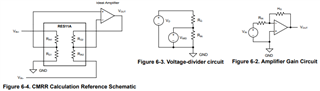
    You may do either in this case. If the op amp's voltage is always positive in your setup, SUB pin may be good to connect to GND. If the op amp's output stage can go either positive or negative. SUB may be connected to -12Vdc rail.

    I do not think that it will make a significant difference. The substrate pin is used to drain any charge buildup in the substrate, minimizing leakage current path and improve noise immunity. 

    If you have other questions, please let us know. 

    Best,

    Raymond

  • Raymond,

    how much dc leakage current -You mentioned - flows to substrate at max. operating temperature?

    At picture from Ryoichi: Is the total resistance value is RIN+RG=1kOhm or the partial resistance RIN=1kOhm?

    Thanks,

    Ralph

    Delete the new  thread: RES11A: RES11A: Question about the GND/SUB connection of RES11A - Amplifiers forum - Amplifiers - TI E2E support forums

  • Hi Ralph,

    how much dc leakage current -You mentioned - flows to substrate at max. operating temperature?

    The resistor IC is fabricated on a Si-substrate that forms PN junctions with the resistor layers and metallization. If the substrate is left floating or connected to an unknown potential, parasitic PN junctions can become forward biased by DC leakage currents. This forward bias potential creates unwanted leakage currents through the substrate junctions, which may cause DC errors in the resistor values, nonlinearity effects, and/or increased noise or drift in precision applications. 

    By terminating the Si substrate to a known potential (e.g. GND, low noise and low impedance node or most negative potential in the circuit), the substrate PN junction is reverse biased internally at Si level, and such "errors" won't affect the precision applications. 

    I am unable to quantify the DC leakage current level, since it is not characterized. If you follow the datasheet's recommendation, this should not be a factor.

    If you have other questions, please let me know. 

    Best,

    Raymond 


  • Hi Raymond,

    Thanks for your reply! That's what I thought too. But the Maximum common mode voltage (any pin to GND/SUB) is specified as ±135V. (neg. voltage)

    Is the total resistance value is RIN+RG=1kOhm or the partial resistance value is RIN=1kOhm?

    Best regards,

    Ralph

  • Hi Ralph, 

    Is the total resistance value is RIN+RG=1kOhm or the partial resistance value is RIN=1kOhm?

    In RES11A, the common-mode voltage or Vcm is defined as the voltage at any device pin measured with respect to the device's GND/SUB pin. So you have to show me the circuit first.  

    In the article and RES11A's datasheet, here is how Vcm is defined for the difference amplifier, where RES11A will be used (typical usage). 

    https://www.ti.com/lit/an/sboa582/sboa582.pdf?ts=1755245190598

    In the above article, it uses the noise gain or voltage divider at the input source. which it makes the math calculation easier (the source common-mode  input). From the op amp's datasheet point of view, the input common mode voltage typically refers to the op amp's input pins, similar Vcm definition, where Vcm_pins = (Vin+ + Vin-)/2. 

    But the Maximum common mode voltage (any pin to GND/SUB) is specified as ±135V. (neg. voltage)

    For the specification below, ±135V Vcm_max refers to the source common-mode described in the sboa582 app note., which is in a difference amplifier configuration. The Vcm mode is defined in this context, and referenced to GND/SUB pin only.  

    The RES11A's abs. max. ratings is very specific, the total resistance value is RIN+RG=2kOhm refers to ±77.5 Vcm_max (a example in the table below), see the current and  the estimated max. power dissipation specification (i think that these ratings refer to sustained voltage, current or power dissipation). 


    If you have other questions, please let me know. 

    Best,

    Raymond