This thread has been locked.

If you have a related question, please click the "Ask a related question" button in the top right corner. The newly created question will be automatically linked to this question.

LM2903-Q1: Changes Revsion L → M

Part Number: LM2903-Q1
Other Parts Discussed in Thread: LM339

Tool/software:

Hi all,

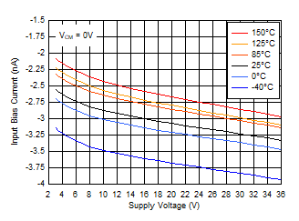
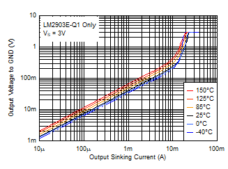
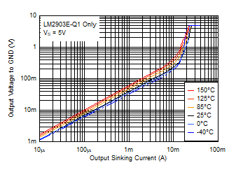
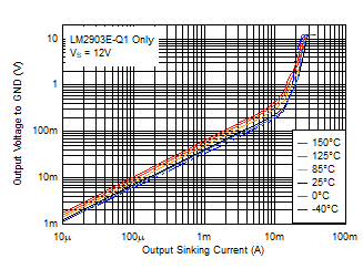
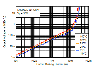
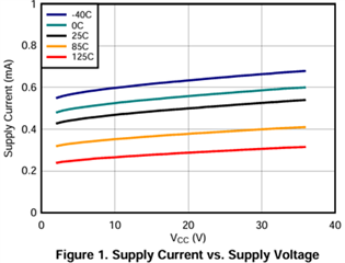
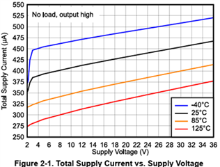
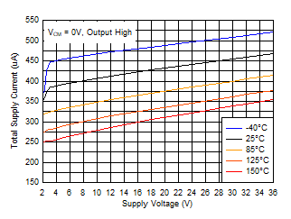
I have some questions about the graph Updated Typical Characteristics below.

1) I understand that each graph has different measurement conditions. Please tell me each measurement condition.

Revision L→Figure 1

Revision M→Figure 2-1TA = 25°C, VS = 5V, RPULLUP = 5.1k, CL = 15pF, VCM = 0V, VUNDERDRIVE = 100mV, VOVERDRIVE = 100mV unless otherwise

L:M

2) I think there is a difference in the block diagram.

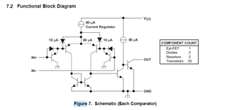
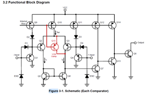
Q9~12, Q14 and Q15 have been added.

This circuit was changed due to the addition of the previous process plant.

Is that correct? Or was it there originally?

Best Regards,

Ryusuke

  • 1. The conditions are the same; the new die has a smaller supply current.

    2. See sections 2 and 3 of the Application Design Guidelines for LM393 Family Comparators for details.

  • Hello Ryusuke,

    As Clemens mentioned, please see the appnote. That is all explained there.Section 6 explains the circuit changes.

     Application Design Guidelines for LM339, LM393, TL331 Family Comparators

    When operated within the datasheet limits, the operation is identical.

  • Hi Paul and Clemens,

    (1)About thermal resistance
    In the Rev.G data sheet, the LM2903E-Q1 thermal resistance value is shown in section 6.5.
    In the Rev.M data sheet, the table in section 2.8 is grouped together without distinction of suffix.
    I would like to know the thermal resistance value of LM2903E-Q1, if available.

    (2)About Supply Current vs. Supply Voltage
    In Figure 2 of the Rev.G data sheet, there is a graph of Supply Current vs. Supply Voltage for LM2903E-Q1.
    The characteristics at − 40°C, 25°C, 125°C, and 150°C are shown.
    I think the corresponding graph in the Rev.M data sheet is Figure 2-1, but there is only a graph up to 125°C. I would like to know the characteristics of LM2903E-Q1 at 150°C.

    (3)About Input Bias Current
    In the electrical characteristic table in Section 6.6 of the Rev.G data sheet, the input bias current
    is described as -25 nA (typ) to -250 nA (max) at 25°C.
    On the other hand, the measurement graph of the bias current in Figure 4 shows approximately +30 nA to +35 nA (25°C).
    Should I recognize it as an absolute value?
    By the way, Figure 2-15 in the Rev.M data sheet shows approximately -2.5 nA to -3.5 nA (25°C).
    You can understand that the measured value is less than the typ value shown in the table.

    Best Regards,

    Ryusuke

  • Hello Ryusuke,

    (1) After the PCN's take place, all devices will use similar die size and leadframes - so the thermal values are the same for all devices - regardless of suffix.

    (2) Will look to see if we have some data.

    (3) Because of the mix of PCN and non-PCN material on the market, it was decided to not change the electrical table typical until the market is the majority of PCN material. The new die bias current is about 10x less at 3-5nA. See graphs 2-15 through 2-18.

    The input is a bipolar PNP input stage. Base (bias) current flows OUT of the input pin towards ground, and the convention is that current coming out of pin is a negative value. Since it is a base current, it is constant and in one direction.

    For more info, see section 6 of the LM339 family appnote:

    Application Design Guidelines for LM339, LM393, TL331 Family Comparators

    Please refer to the Rev.M datasheet. We are no longer producing the "original' Ji1 material, so we have purged the old graphs.

  • Hi Paul,

    Thank you for your answer.

    2)I look forward to your answer.

    Best Regards,

    Ryusuke

  • Hi Paul,

    How is your progress?

    I would appriciate if you could reply the answer.

    Best Regards,

    Ryusuke

  • Hello Ryusuke,

    Here is a preview...they are coming slowly...

    LM2903E-Q1 Supply Current vs. Supply Voltage

     .

    I'm working on the bias current next..

  • Here is the bias current:

    LM2903E-Q1 Bias Current vs. Supply Voltage:

  • And here are some output swing curves:

  • Hi, Paul.

    Thank you for your very kind response. I will refer to it.

    Best Regards,

    Ryusuke