This thread has been locked.

If you have a related question, please click the "Ask a related question" button in the top right corner. The newly created question will be automatically linked to this question.

INA851: INA851

Part Number: INA851
Other Parts Discussed in Thread: INA848

Tool/software:

Hi,

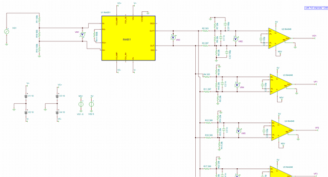
I'm using INA851 to drive a small signal to multiple instrumentation amplifiers for a calibration path,

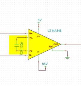
the INA851 is feeding in parallel multiple instrumentation amplifiers with gain 2000 ( INA848), 

one main problem is due to the offset voltage in its output which is amplified more after the INA848, i'm wondering if it can be improved or is there another FDA amplifier solution,

the other problem is the capacitive load but we might can live with it,

the INA 851 is used to buffer between a precision voltage divider that served as attenuator for calibration the gain of the INA848 amps used for sampaling analog signals by on bpard ADCs

the voltage divider cannot be loaded by the buffer because it made by 100K and 1K resistor values this is the reason i'm using the FDA instrumentation amp INA851.

 I

 can see the offset also in TINA simulation which is about 300uV,

Please advice,

Thanks,

Barak

  • Hi Barak, 

    Could you clarify how small this signal is on the input? What are you trying to scale up on the output and the desired output range? 

    Regards,
    Ashley

  • Hi Ashley,

    In general, I have implemented an accurate attenuator using resistor dividers and the buffer INA851. This is used to calibrate the signal path from the INA848 and its input filter to the input of the onboard ADC.

    I'm measuring the input of the attenuator using the onboard ADC, as well as at the INA848 output. By knowing the attenuator value, we can calculate the total gain of the signal path. (the reason I'm using the attenuator that is hard to measure precisely a very small signal by the on board ADC).

    In the application, we need to amplify a sensor made from a coil to measure a magnetic field.

    The input signal in the simulation is 1 Vp-p divided by 401.

    The desired output range is a minimum of 10 Vp-p.

    Thanks,

    Barak

  • Hi Barak, 

    Could you clarify what ADC you are driving and what the input range of this ADC needs to be? Also, what is the impedance of the sensor output? 

    I also noticed in the simulation image you showed in your original post, the component where RG usually is for INA848 has a capacitor instead. Is this intentional?

    Regards,
    Ashley

  • Hi, sorry for the late reply; I missed your message.

    I'm using the ADC LTC2348ILX-18, and the input range is ±10V. The sensors have an impedance of approximately 350 ohms at 20kHz (300 ohms resistive and 50 ohms reactance of the sensor coil). However, in this setup, I connected the INA851 instead of the sensors to measure the amplifier's total gain for self-calibration.

    Regarding the Rg, I have connected a 600kΩ resistor to the INA851 to achieve a gain of 1.

    In real-world operation, I observe a stability issue with the output offset, specifically an oscillation around 9MHz at the INA851 outputs, which is not present in the simulation.

    I wonder what can be done to address:

    1. Offset compensation
    2. The oscillation caused by the capacitive load and why this 9MHz oscillation is not seen in TINA simulations

    Additionally, I've connected non-inverting buffers—one to Out+ and the other to Out- of the INA851—to better drive the capacitive load. However, stability issues also persist with this configuration. The buffers are connected directly to the outputs, but each buffer's input capacitance is small,

    Thanks,

    Barak

  • Hi Barak, 

    Do you have images to show what this oscillation looks like? It would also be helpful if you could provide the simulation file as well. 

    Could you also clarify what you mean by replacing the INA851 instead of the sensors? Is the INA851 used in the real-world operation to measure the sensor? 

    Also, I meant the Rg of the second stage, INA848. I see capacitors connected to the Rg pins. 

    Regards,
    Ashley

  • Hi Ashley,

    I have replied to your message in the Email, did you get it?

    Thanks,

    Barak

  • Hi Barak, 

    I did not see a response from you. Could you post here again? 

    Regards,
    Ashley