This thread has been locked.

If you have a related question, please click the "Ask a related question" button in the top right corner. The newly created question will be automatically linked to this question.

INA333: INA333

Part Number: INA333


Tool/software:

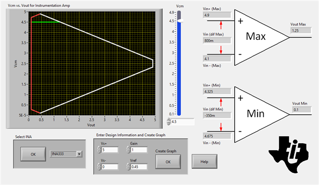
Fig. 21 in the INA333 datasheet is generated with a VREF of 0V, will the output voltage just go up by 0.45V if I apply a 0.45V voltage source to the VREF pin? For instance, at input common mode of 4.5V in Fig. 21, the output is 1V when the VREF is 0V, will the output go to 1.45V if I apply 0.45V at the VREF pin? Again referring to Fig. 21, if I apply 4.5V at VIN+ and 4.503V at Vin-, set the gain to 100, and apply 0.45V at the VREF pin, what is the output voltage going to be? I am thinking that the output should be = -0.003x100+0.45=0.15. Since the differential input voltage is negative, I wonder if VREF can shift the output to positive level so that the circuit will work properly.

  • Hi Kuok,

    We have this very useful tool called the Analog Engineer's Calculator! These Vcm vs Vout plots are a bit confusing. I always use them to get a better understanding of the effects when I change the Vcm or need a specific output voltage range. Let me show you. 

    For instance, at input common mode of 4.5V in Fig. 21, the output is 1V when the VREF is 0V, will the output go to 1.45V if I apply 0.45V at the VREF pin?

    Starting with the first condition. Vcm =4.5V, Vref = 0V, Vs+ = 5V, and Vs- = 0V what will the output voltage range be? It's not quite 1V, it's actually a max of 0.8V. 

    Plugging in the same values but with Vref = 0.45V, we now see the output voltage shift up to 1.25V. 

    Again referring to Fig. 21, if I apply 4.5V at VIN+ and 4.503V at Vin-, set the gain to 100, and apply 0.45V at the VREF pin, what is the output voltage going to be?

    The big change here is the input voltage range now shifts when changing the gain to 100, which makes sense. 

    I highly suggest you download the calculator and check it out! 

    Best Regards,

    Robert Clifton

  • Thanks, Robert! This is what I was expecting, but I just wanted to make sure it works as expected. BTW, if I raise the Vs to 5.5V, I assume it will give me 1.6V + 0.45V, so the output will be 2.05V, right? I want larger output amplitude. I tried downloading the calculator, but I wasn't able to get it to work somehow, maybe I will spend some time figuring it out.

  • Hi Kuok,

    Weird that the calculator isn't downloading. 

    Increasing the supply voltage allows the output to go up to 2.25V actually. 

    Best Regards,

    Robert Clifton

  • Good, so my thought was on the right track. Thanks, this has been really awesome tech support - we didn't have it this good when I was designing mixed-signal ICs at TI for 11 years.

  • Hi Kuok,

    Happy to help! 

    we didn't have it this good when I was designing mixed-signal ICs at TI for 11 years.

    This tool has been so happy to have this tool as it's made life so much easier! 

    Best Regards,

    Robert Clifton 

  • One more questions, how much does temperature affect the common mode input range? The INA333 datasheet specifies, +/-0.1V from the rails, but that's listed at 25C. I imagine it will get reduce some over -40C to 125C, my question is by how much?

  • Hi Kuok,

    It's not something that we tested with the INA333. Our newer devices will have this data, but it wasn't something we characterized for the INA333. 

    Is there a particular reason you are needing this? Are you expecting to operate close to the operating range of the boundary plot? 

    Best Regards,

    Robert Clifton