Part Number: OPA858
Tool/software:
Hi, I´m doing simulations with the OPA858 device and I am getting some peaks in the frequency responce that I was not expecting. Then I moved to do some basic simulation to try to obtain and verify the operational parameters and there is some variations in the frequency response that i was not expecting.
I´m trying to replicate the simulations idea of the document "What You Need to Know about Transimpedance Amplifiers – Part 1" at page 2 for determining the magnitude and phase of loop gain, AOL and 1/β. I was expecting a curve like this one stated iin the document
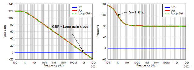
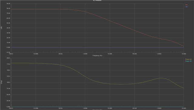
but I rather obtained this one
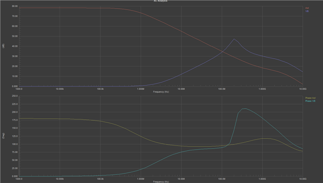
see that close to the 1GHz there is something in the magnitude response that introduce som kind of zero and then a pole. The phase for the Aol also suffer some perturrbation at the same frequenccy.
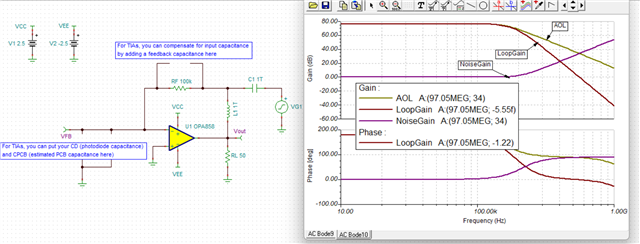
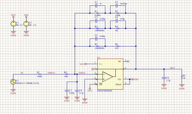
the circuit I´m simulatin is this one
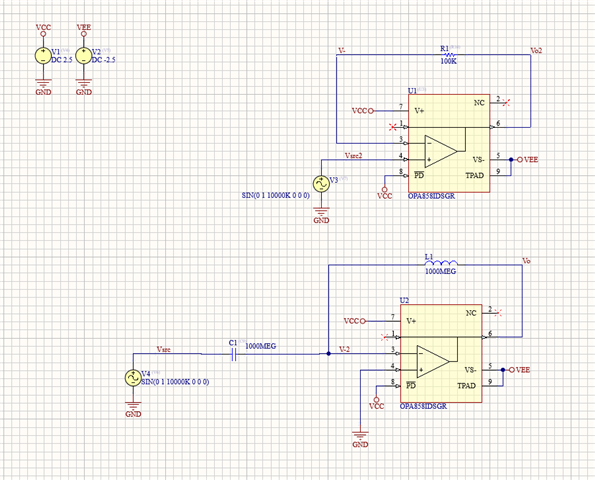
The model I´m using I extracted from the opa858 website andd Im simulating in altium.
I defined the Aol in the lower circuit as Vo/V-2 and the B in the uppere circuit as V-/V02 and then calculatedd th e1/B
When I change the R1 value fromm 100K to 0.0001 ohm I obtained this result
Can you help understand why Am I having this result?
The problem started because I was simulating this circuit
and I´m obtainning this result
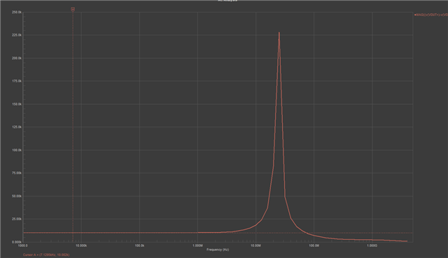
here I[m trying to get bacck the R8 resistor value using the equation (v(VDUT+)-v(VDUT-))/((v(VDUT-)-v(OUT))/100Kohm)
for the low frequencies I obtain the correct value, but then there iis this peak at the 25.14 MHz that i was not expecting and need to understand what is happening for removing this peak.
Thanks you very much