Tool/software:
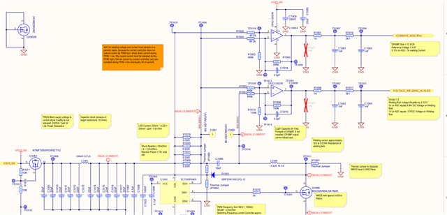
In my application, a LED Current controller drives current up to 16A.
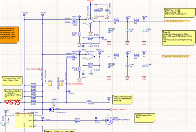
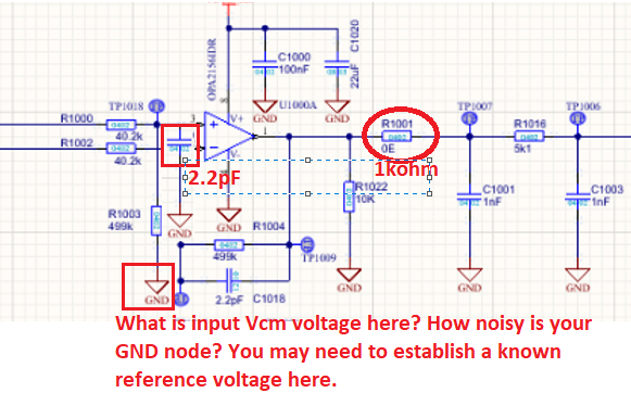
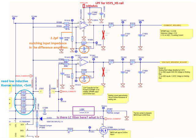
4 in parallel sensing resistors create a sense resistor of 12.5mOhm. The voltage accross the sense resistor will be amplified by OPA2156 by factor 12.4. The voltage accross the load will be attenuated by factor 2.5 with the same Amplifier OPA2156.
Referring to the schematic:
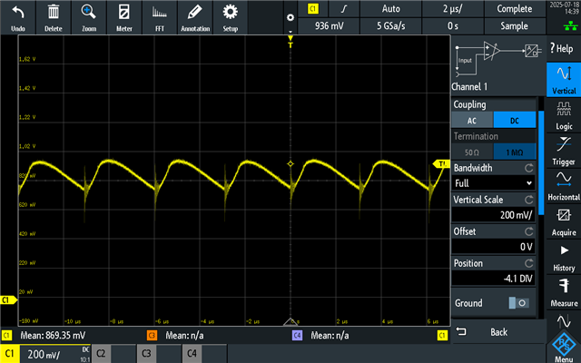
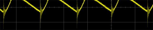
When the current controller is operational, during ON time, a certain voltage drop on VSYS can be seen, which is reflected fully on the output of U1000A.
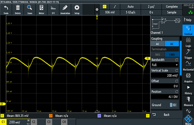
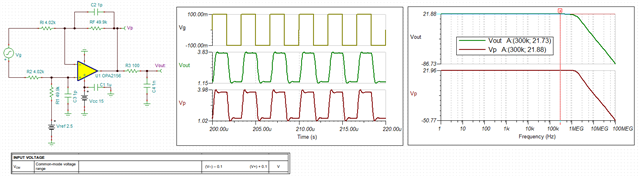
The PWM frequency of the current controller is between 250kHz and 300kHz. The OPAMP has a fairly high slew rate and GBW product of 25MHz, which is results in around 2MHz Bandwith with Gain 12.41. Yet, the OPAMP seems not to amplfied the difference but also the voltage swing von VSYS. I am seeing a voltage swing of around 200mV on the output of U1000A, while the input swings as well at around 200mV.
VSYS can be from 10V to 26V. We see very different output results from U1000A between these voltage but I should be same.
I suspect the feedback current to be too low on R1004 and reduced R1004 / R1003 to 49.9k and reduced R1000 / R1002 to 4.02k. This led to some minor improvement, but yet the performance of the current amplififer is not good enough for our application.
U1000B works just fine, we see almost no output voltage swing (I suspect attenutation by 2.5 helps a lot).
Now we need hints to improve the measurement accuracy of U1000A.
The measurement is taken at TP1006.
Thanks Martin