This thread has been locked.

If you have a related question, please click the "Ask a related question" button in the top right corner. The newly created question will be automatically linked to this question.

INA190: INA190’s output oscillates when placed in "parallel" to INA236.

Part Number: INA190
Other Parts Discussed in Thread: INA236, , INA219

Tool/software:

Hello everyone.

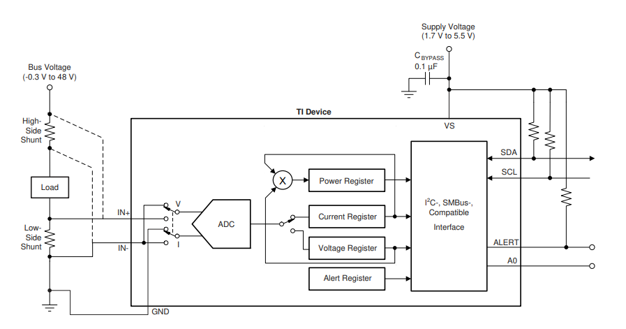
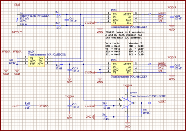
I need to measure the voltage applied to a load and the current that goes into it. Power comes from VBAT and goes to the load through a 10 mΩ shunt resistor (Rs).

Voltage and "high" current (up to 8.192 A based on INA236 full scale) is measured with the top INA236BIDDFR (INAH) with no problems.

I also want to measure "low" current, for when the DUT (device under test) is sleeping. For that I use the INA190A3IDCKR (GAIN) with a gain of 100, that lets me measure up to 20.48 mA with a LSB of 625 nA in a seconf INA236.

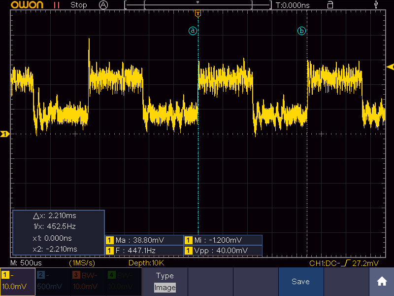
The issue I am having is that the GAIN output is oscillating. I found that the oscillation goes away if I remove the INAH IC. I also tried removing Ra1, with no effect (with INAH still soldered).

The oscillation itself, is a square wave from 10 mV (fixed) to 20 or 25 mV (dependent on the load current, which was around 4 mA when scope capture was taken) with a frequency of 450 Hz.

May you suggest an alternative to the INA190 or, maybe, a completely different approach with another IC that lets me measure “high” and “low” currents?

I haven’t tried it yet, but perhaps, adding a positive reference to the INA190 to get away from the ground rail helps eliminate its output oscillation.

  • Hi Agustin,

    Looking at your oscilloscope shot, it appears to be switching from GND to ~12mV. This switching behavior is due to the sampling ADC in the INA236 that switches measurement between Vbus, Vshunt and current. There is also a 1.05 MOhm resistor to GND on the IN- pin internally that draws current when ADC is sampling Vbus.

    To eliminate this oscillation effect you could: 

    1. Alter the register settings such that Vbus is not measured at all (Configuration Register -> MODE -> Continuous shunt voltage)

    2. Alter the conversion time of the bus measurement, make it longer

    3. Remove the 10 ohms resistors (R01/R02) in the sense line.

    Assuming your Vbat is 12V, when the ADC is sampling Vbus, the current coming though IN+ is " I_IN = 12/(1.05M) ~1.14 e-5 A. When you have 10 ohm resistors, then there'll be a voltage drop across them of " V_drop = 1.14 e-5 A* 10 ~ 115 uV , after a gain of 100V/V, the INA190 output is ~ 11.5mV." This the voltage the output of the INA190 is oscillating to, so by removing the resistors there'll be no voltage drop in the sense line and the oscillation should stop

    Best,
    Mallika Senthil

  • That looks promising. I'll give it a try,

    Thank you

  • Confirmed. Measuring only current with INAH removes the oscillation in the INA190's output.

    Now I have a new problem: I can´t measure the bus voltage.  I don't want to reconfigure the INAH every time I need to make the measurement. Therefore I must change the design. Can you help me this?

    In our previous PCB, we used 2 shunt resistors in series, one with low value (10 mΩ) for high currents and one with high value (25 Ω) for low currents (that could by bypassed). Each shunt had it own INA219. The issue here was that the INA219 did now work correctly with such a high value shunt. I changed the design mostly because I didn't like the fact that the current to the load had to take a different path if it was big or small.

    I found in the datasheet that the INA236 can work with "large" shunts. I can't see how large "large" is.

    Thank you very much for all the help.

  • Hi Agustin,

    There isn't a specified upper limit to how large a Rshunt you can use. This depends on how small a current you want to measure and how much error you can tolerate. Please see our Error-Tool Calculator, you can use it to find the best Shunt for your system.

     https://www.ti.com/tool/CS-AMPLIFIER-ERROR-TOOL

    Best,
    Mallika Senthil

  • Thank you very much Mallika