Other Parts Discussed in Thread: OPA2992, OPA4992, , OPA2196, TLV2197-Q1
Tool/software:

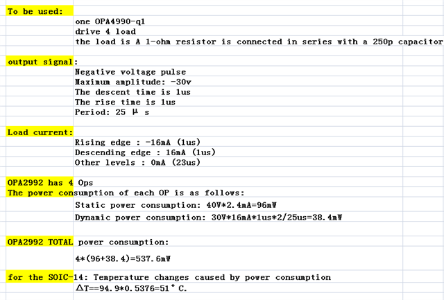
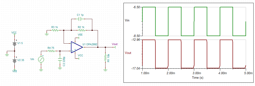
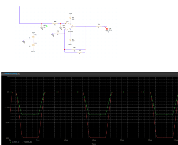 HI , see the sch , is it OPA2992 (OPA4992 ) can work at vcc=5v and vee=-35v , input -15v , and want to get -15v*2=-30V , is it ok ? thanks.
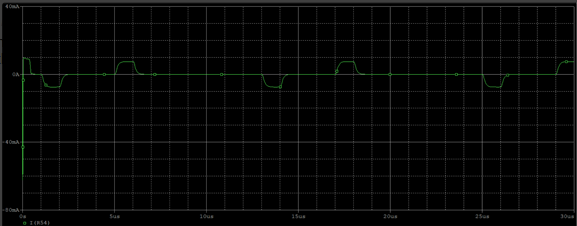
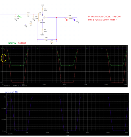
and we can find the output is pulled down at the power up ( the RED wire , 0us~0.5us) , why ? What methods can be used to avoid it?


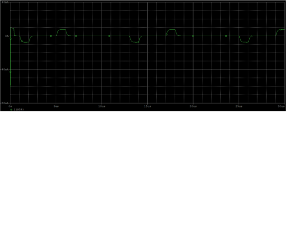 mA , look like the OPA2992 can not provide ,so ,the output is pulled down . now , I don't know ,why has so high inrush current .
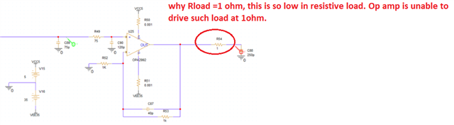

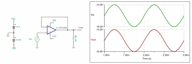
 There should be no mistakes, right? Can it be used like this?