This thread has been locked.

If you have a related question, please click the "Ask a related question" button in the top right corner. The newly created question will be automatically linked to this question.

INA128: TIDU990 DC rejection integrator vs HPF

Part Number: INA128
Other Parts Discussed in Thread: OPA189, INA849

Tool/software:

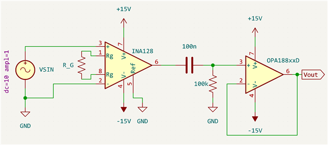
Hello, I have a question regarding the circuit presented in article TIDU990. This is the circuit in question:

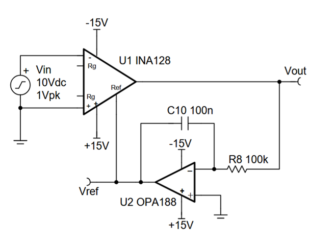
The circuit is presented as a superior alternative to putting RC highpass filters at both inputs of the instrumentation amplifier, and the advantages are discussed. My question is: what are the tradeoffs to, instead of feeding the integrator into the REF pin of the inamp, following the inamp with an active HPF with the same RC values of the integrator. For clarity, here is the circuit:

  • Hi Jacob, 

    Welcome to E2E! 

    Let me simulate this on my side and see if I can better understand the tradeoffs of these two implementations.

    Regards,
    Ashley

  • Hi Jacob,

    What RG are you setting for the INA128? Are you going to use it in a gain of 1? 

    Regards,
    Ashley

  • It would be a gain of 50 in my case

  • Hi Jacob, 

    Is your input signal the same as the reference design? With a gain of 50, you would be hitting the output swing limit of the INA128. 

    Regards,
    Ashley

  • Oh good catch. My input signals would be +/-200mV or smaller in amplitude. In my application, I'll probably be using an INA849 and an OPA189 where applicable, so I'm more concerned about general behavior. 

    Also sorry for the slow replies. I've been out with a back injury.

  • Hi Jacob, 

    Thank you for the clarification. In general, the circuit you have proposed should work, but the limitation would be the Vcm vs Vout behavior for the INA849. Since you are not changing the Vref with the integrator circuit, you will need to make sure the circuit is in linear operation with the conditions set. 

    The Analog Engineer's Calculator shows this behavior and allows you to input your application conditions to verify your input/output limits. 

    To clarify, is the Vdiff at the inputs would be +/-200mV? Is there an input common mode voltage applied to the input? 

    Thank you!

    Regards,
    Ashley

  • Thanks Ashley, I should get this calculator and play around with some scenarios.

    For my application, the signals at the input are usually small signals riding on top of a relatively large DC offset, very similar to electrocardiogram (ECG) signals. The only common mode signal I can think of would be 60Hz from building power. From my own simulation, it looks like they perform about the same, but in my bench testing, the integrator solution gives me ~200mV of DC offset with shorted inputs after settling. 

    My original question still stands: does the integrator give me any benefit vs the HPF in general, or are they basically the same? My intuition tells me that there should be some benefit to having fewer components directly in the signal chain, but the DC offset that I'm seeing on the bench makes me not so sure.

  • Hi Jacob, 

    From simulation, I could not see major tradeoffs between the two implementations. The only difference is the loading effect of a capacitor versus a resistor on the INA but I do not believe it should impact the offset. 

    Do you also see the 200mV of offset on the HPF solution? 

    I will also try to test the two solutions on bench on my side. 

    Regards,
    Ashley

  • I don't see the offset with the HPF solution, but I should also mention that I am aiming for a very low corner frequency (~1mHz), so I'm using a 22uF film capacitor and a 7.5MOhm thin film resistor. Unless that changes your conclusion (which I wouldn't be surprised if it did), I think you've answered my question. Thanks Ashley.