A related question is a question created from another question. When the related question is created, it will be automatically linked to the original question.
If you have a related question, please click the "Ask a related question" button in the top right corner. The newly created question will be automatically linked to this question.
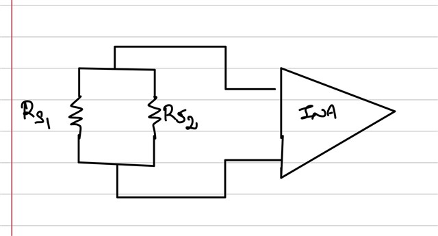
When placing 2 Rshunt in parallel, it's important to keep the the trace length of IN+ and IN- identical and to ensure the resistors are matched carefully to avoid uneven current distribution. Please note, when matching resistance, you'll need to take into account the resistance due to solder between Rshunt and the resistor pad as well.
Best practice would be to place the shunts as close together as possible and then run the sense line trace from the middle of the connection as shown below:
As a side note, we are working on writing an application note for this use case, it should be released near the end of the year.
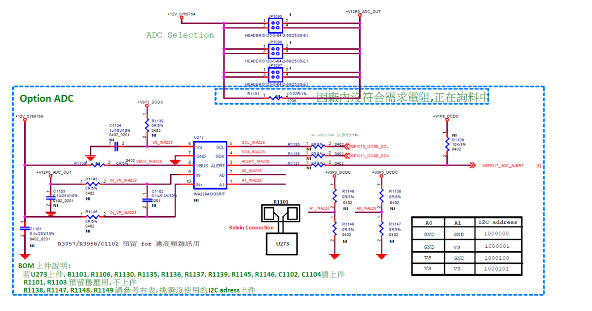
Please help review below design if need any modify.
(Use case: 12V voltage, maximum current 4.5A, with no expected low-current measurements)
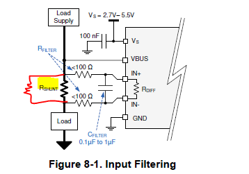
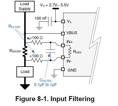
Based on the above voltage and current requirements, how should the R filter and C filter values be selected? Are they mandatory? Is it acceptable to place only the capacitor without the resistor? Is the primary goal to filter out noise above 1MHz? Any layout recommendations?
Besides placing Rshunt directly in series, are there any alternative design methods?
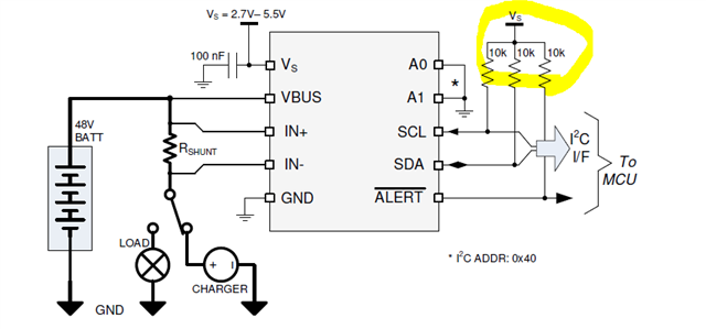
Can the SCL/SDA lines be driven directly by 1.8V logic? Although the VIH is specified as ≥1.2V, the diagram shows the pull-up resistors tied to VSS
Is it acceptable to place capacitors from IN+ and IN– to ground for voltage stabilization (such as the capacitors labeled C1101/C1103 in the circuit)? If yes, what capacitor values would you recommend?
Based on the above voltage and current requirements, how should the R filter and C filter values be selected? Are they mandatory? Is it acceptable to place only the capacitor without the resistor? Is the primary goal to filter out noise above 1MHz? Any layout recommendations?
The RC is used to create a filter for noise, as detailed in section 8.1.4 of the datasheet. The filtering is optional and depends on the noisiness of your system. You can use just a capacitor, generally we recommend the value to be less than 1uF.
Besides placing Rshunt directly in series, are there any alternative design methods?
Our current sense amplifiers monitor current by measuring the voltage drop across Rshunt and then amplifying it to the output. So you need Rshunt to be in series with Vbus for the INA device to function. What application are you looking for an alternate design to?
Is it acceptable to place capacitors from IN+ and IN– to ground for voltage stabilization (such as the capacitors labeled C1101/C1103 in the circuit)? If yes, what capacitor values would you recommend?
No we generally don't recommend capacitors to GND because they can introduce additional input bias current into the device if you're operating on AC or the signal is switching.
Please see the following links for more information:
Your schematic needs to be redesigned with the comments above in mind, you definitely will need a Rshunt for the INA device to work. For layout guidance, please see section 9 and 10 of the datasheet.
Aside from the shunt, I don't have anything more to add at the moment, please feel free to resubmit your modified schematic once it is finalized for us to check.