Tool/software:
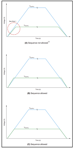
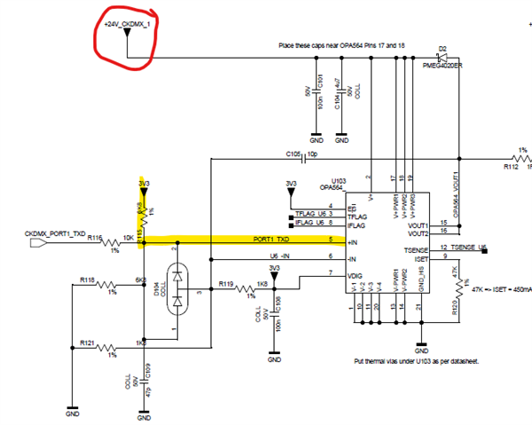
In my design +IN input of OPA is connected to 3.3V through a 6.8K pull up. And 24V supply will be provided when the communication is needed.
Is there any problem in this scheme?
Tool/software:
In my design +IN input of OPA is connected to 3.3V through a 6.8K pull up. And 24V supply will be provided when the communication is needed.
Is there any problem in this scheme?