Other Parts Discussed in Thread: OPA192, INA333
Tool/software:
Hi E2E,
Problem Description:
[Application]
We're using three OPA192-based differential amplifier circuits to measure phase-to-neutral voltages (L1-N, L2-N, L3-N) of a 3-phase 400V AC system. Each amplifier senses voltage via resistor dividers, with all three circuits sharing the same neutral point (N) as reference.
[Observation]
When enabling only one phase (e.g., L1 = 494V, others = 0V), the output is stable (e.g., ~7.8630V).
However, when enabling all three phases together, slight variations occur in each output (~0.0002V), even if the input voltages remain the same.
This issue is defined as poor cross regulation, where changes in one channel affect others.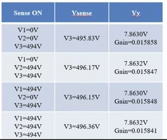
Suspected Root Cause:
-
Shared Neutral Point Drift:
The "N" point is not a perfect ground. When all three sense paths share N as their negative input, any loading or imbalance can cause voltage drift, impacting all channels. -
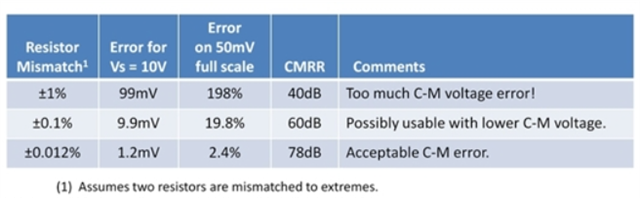
OPA-based Differential Amplifier CMRR Limitation:
The discrete differential configuration has limited common-mode rejection. It is more sensitive to neutral point fluctuations compared to an instrumentation amplifier. But the OPA219 CMRR 150dB max. -
High Impedance Design:
We're using high-value resistors (e.g., R1 = 820k || 820k || 820k ≈ 273kΩ, R2 = 39kΩ) to reduce power, but this increases sensitivity to leakage, parasitics, and noise.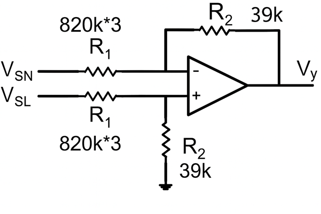
Current Design Snapshot:
-
Input: 3-phase 400VAC, each phase through voltage divider to OPA192 differential amplifier
-
All three amplifier circuits share the same N as reference
-
Gain ≈ 0.01585
-
Output range: ~7.8630V per phase (at ~494V input)
Request for Support:
We would appreciate any of the following:
-
Confirmation on whether this cross-regulation issue is inherent to shared-N OPA-based structures
-
Design suggestion using OPA192 to improve isolation/stability
-
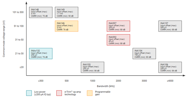
Recommendation on switching to INA (e.g., INA333) or other instrumentation amplifiers
-
Any known TI reference designs for accurate 3-phase voltage sensing
Thanks, and regards