Tool/software:
Hi Team
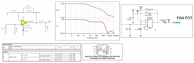
Customer Siemens used below OPA2277 circuit. (Rf/R839 = R1/R838 = 6.19Kohm)
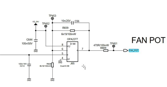
They have been using below test way to decide if it the IC/functions well in their production line:
- Input 0V to PIN5
- Measure Vout (TP451)
- They expected Vout should be within 1V
- Actually, in previous material shipped, OPA2277 did performed like this, means Vout within 1V for 0V VIN.
But recently, for their new ordered materials, they found, in total 69 pcs devices, there are:
- 28 pcs shows Vout within 1V range [38mV to 1V] for 0V VIN
- 41 pcs shows Vout in range of [1V and 2.3V] for 0V VIN
Therefore, they wonder if there is any change happened on OPA2277 manufacturing. (There seems to be a PCN happened)
For questions:
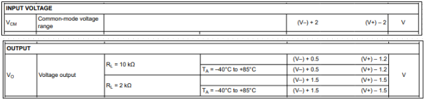
1) If above testing way make sense? Is the 0V input already violated the spec. of input range? [V- + 2 to V+ - 2]
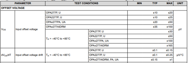
2) Why the newest 69 pcs shown different Vout distributions? Which IC spec. impact this?
3) I think there is some modification required for this circuit. As VOUT for the load of FAN_POT would be starting to work on 2V voltage. But currently circuit seems not able to be guarantee min. output at 2V, unless they change circuit to a Follower. Then VIN 2V can output VOUT 2V, without violation. Is this understanding correctly?
Thanks!
Regards
Rocky