Tool/software:
Hello,
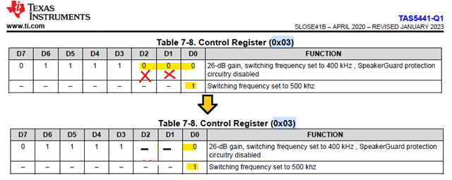
First row of Table 7-4 shows Data bits [D2 D1 D0] = [0 0 0] to set the Switching Frequency to 400kHz whereas on second row, when D0 = "1" , the Switching Frequency is set to 500kHz.
I think only D0 is used to set the Switching (i.e D0=0 sets it to 400kHz, D0=1 sets it to 500kHz)
In this case, the bits D1 and D2 on first row should show "-" instead of "0"
Can you please confirm?
Thanks
Chirag