This thread has been locked.

If you have a related question, please click the "Ask a related question" button in the top right corner. The newly created question will be automatically linked to this question.

TLV9352: Design suggestion, Component selection for Howland Current Source

Part Number: TLV9352

Tool/software:

Hi E2E

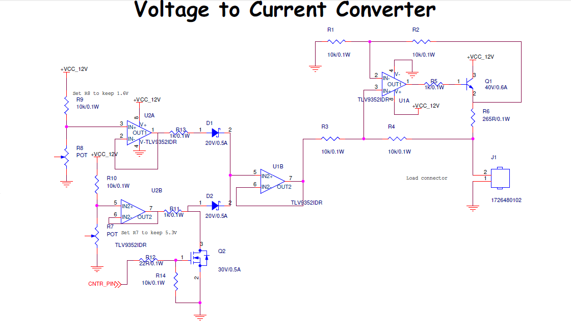
I want to design an Howland current source, In my design
The first part is where I can tune and control the various basing voltage of the Howland current source non inverting refernce.
In First part, its just an switch and buffer to set the biasing voltage.
In the second part, I have howland current with with Sense resistor of 265R. I want a detailed approach right from selection of Bjt, biasing and feedback resistor, also review and provide feedback on the same.
My design requirements is to have 6.5mA to 18mA  when biasing voltage from U1B.7 is variaing with set limints (flexbile to tune with the POTS) 

Thanks in Advance 

Regards

Chaitanya 

  • Hi Chaitanya,

    I'd be happy to help with this. I have a few comments on the design so far:

    1. The output short circuit current (Isc) of the TLV9352 is +/- 60mA, and since your max output current is 18mA, you may not need the transistor on the output of the amplifier. 
    2. It looks like some of the junctions in your schematic may not be connected (for example, the junction between D2, R11, and Q2 doesn't have a tie dot), but it could just be the schematic tool you're using.
    3. You should select a resistor for R6 with a higher power rating than 0.1W, as the power dissipated through the resistor at the full 18mA current is approaching 0.1W.

    For more information on designing a Howland current pump circuit, I would recommend the following app note: Analysis of Improved Howland Current Pump Configurations

    Best Regards,

    Alex Curtis