This thread has been locked.

If you have a related question, please click the "Ask a related question" button in the top right corner. The newly created question will be automatically linked to this question.

TPA2005D1: Amplifier gain setting does not follow the gain equation

Part Number: TPA2005D1

Tool/software:

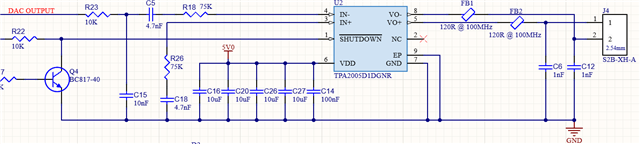
I have an application that uses the TPA2005D1 to amplify a sinusoid signal. it is generated through a DAC and sent through a high pass filter and a low pass filter before the amplifier. However, the amplifier gain does not behave according to the gain formula given in the datasheet, in fact the voltage gain is half of what is expected. I have input resistors set to 75kwhich should produce a gain of 4V/V but only get around 2V/V practically.
What could be the issue here? 

  • Hi Dakshina,

    Can you share your schematic and how/where you're measuring? Perhaps you measure only one side of the Class-D output and not differentially? Have you measured the signal at the input pins of the amp as well, perhaps there's some attenuation at the filters between DAC and amp?
    Another thing to consider is that the filters at the input could represent some specific impedance, which added to Ri causes the gain to no longer see the Ri value only.

    Best regards,
    -Ivan Salazar
    Applications Engineer

  • Hello Ivan, Thank you for the reply

    My schematic looks like this.

    The transistor Q4 enables/disables the amplifier. 

    The DAC is powered by 3.3V and the amplifier is on 5V.

    DAC output is 2.9Vp-p, and it generates 2.6Vp-p at the node between R23 and C5. The differential voltage output is 7.4Vp-p. So I get around 2.8V/V of gain although it should be close to 4V/V.

    I'm measuring the output of the amplifier across a 8 Ohm resistor.

    The amp goes upto 9.2Vp-p before clipping. 

  • Hi Dakshina,

    Thanks for the additional information.

    Have you tried measuring without the output filter connected?
    Another thing I would consider is the tolerance of the input resistors, although the variance would have to be considerable for the gain to be reduced so much.

    Best regards,
    -Ivan Salazar
    Applications Engineer

  • I have been using the this components for different designs and have a few observations.

    1. The gain should be close to 2 as possible. Higher gain settings cause greater THD on the output and unpredictable behavior.

    2. Do not operate near the saturation condition. Output differential voltage of 8-8.5V is the maximum that should be used on a 5V supply.

    2. Your output filters cause attenuation in the output. This will cause the amplifier output to saturate before you can observe the clipping after the output filter.

    I have used 68KOHM as Rin to get 8.5V at the differential output on a 5V supply.

    Hope this helps!

  • I'm using 1% resistors, and the values are within that tolerance.
    The output filter does not attenuate the signal significantly, I can see a few millivolts of a improvement but still below the set gain

  • Hi Dakshina,

    At this point I'm not sure what else could be affecting the gain. If it helps, I can modify an EVM for a similar resistor setting and verify the resulting gain. It'll take some time while I get the EVM in the lab for testing and modifications.

    Emil, thanks for your inputs.

    Best regards,
    -Ivan Salazar
    Applications Engineer

  • Thank you very much Ivan. using 100K or 82K seems to give reasonably close gains, but anything below that (gains above 3.6) seems to behave unpredictable. If you can test this, that would be great.

    Thank you Emil. I will aim for ~8.5V on the output. 

  • Hi Dakshina,

    I was able to locate an EVM, I'll make some time for the test and mods and come back to you by the end of the week.

    Best regards,
    -Ivan Salazar
    Applications Engineer

  • Thank you very much Ivan. Looking forward to it.

  • Hi Dakshina,

    I did some quick test today changing the resistors only (not adjusting the capacitors accordingly), I can also notice the gain deviating as it increases. One more thing to note is that the device seems considerably more prone to oscillations/instability for higher gain levels.

    I would suggest keeping the gain within 2V/V and increase the input signal amplitude if possible. Otherwise consider lower input resistor than calculated to account for the gain deviation and keep a good connection to R load in order to avoid instability due to possible parasitic capacitance on the output traces/cables.

    Best regards,
    -Ivan Salazar
    Applications Engineer

  • Hello Ivan,

    Thank you very much for your help. This confirms what I am observing. I will try to keep the gain close to 2V/V.