Part Number: AMC1400-Q1
Other Parts Discussed in Thread: AMC1400
Tool/software:
Dear TI Support Team,
I hope this message finds you well.
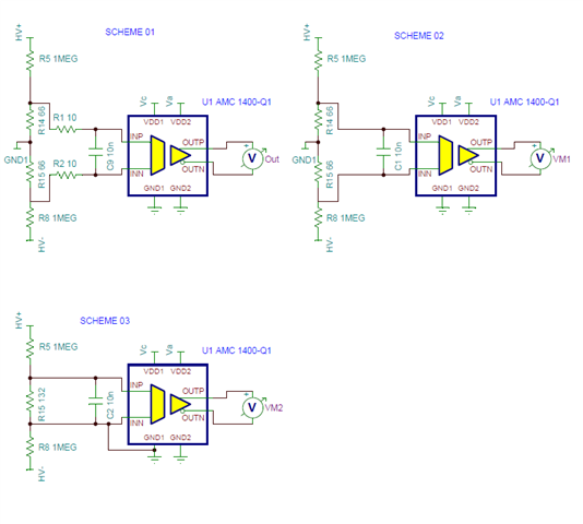
I am currently working with the AMC1400-Q1 and have attached a reference schematic featuring three different configuration schemes (Scheme 01, Scheme 02, and Scheme 03). I would appreciate your guidance on the following points:
Scheme Comparison:
- Scheme 01: This configuration follows the recommendations from the datasheet, kindly confirm if this is the preferred or officially recommended setup by TI?
- Scheme 02: This is the configuration I am currently using in my design, Is Scheme 02 endorsed by TI? Are there any known issues or potential drawbacks with this approach?
Input Adjustment for 100 mV:
- I am aiming to configure the input for a 100-mV differential signal, With the current resistor values (R14 and R15), I’m observing a voltage slightly above 100 mV,
Is it possible to fine-tune the input to achieve exactly 100 mV by placing a resistor in parallel with R14 and/or R15?
- Could this be done with a single resistor, or would a resistor divider network be more appropriate?,
Your guidance on the best method to precisely set the input voltage would be highly appreciated.
Scheme 03 Evaluation:
- Scheme 03 represents an alternative layout. Could you please advise if this configuration is acceptable from TI’s perspective?
- Additionally, how does Scheme 03 compare to Scheme 01 and Scheme 02 in terms of performance, accuracy, and safety?
Capacitor Value Change:
- The current design utilizes a 10 nF capacitor. Would it be acceptable to replace this with either a 22 nF or 47 nF capacitor?
Could you please explain the impact this change would have on bandwidth and filtering characteristics?
I would be grateful for your expert advice and recommendations on these points to ensure the reliability and performance of the design.
Thank You!