This thread has been locked.

If you have a related question, please click the "Ask a related question" button in the top right corner. The newly created question will be automatically linked to this question.

INA149-EP: INA149 as current sensor

Part Number: INA149-EP
Other Parts Discussed in Thread: INA149

Tool/software:

Hi, 

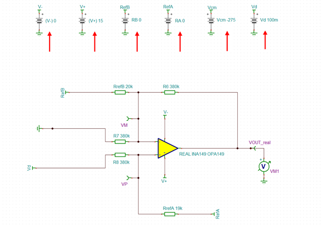
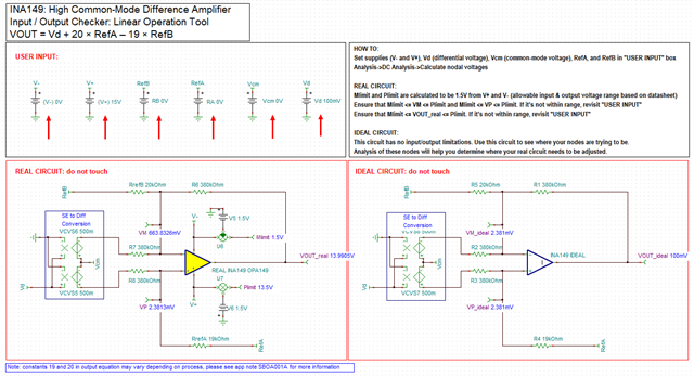
I am trying to use INA149 as a current sensor. I preferred INA149 for its high VCM capability. I want to use an unidirectional power supply, VCC= +5V. This is the model I am simulating with.


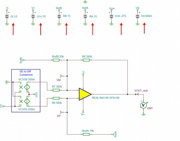
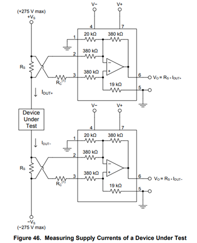
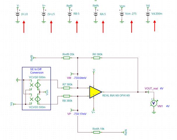
In the simulation, when I reduce the biasing to +5V to V+ and GND to V- with VREFA = +5V. VREFB = +5V (as suggested in the datasheet),  the output saturates to 4V irrespective of the input.

Could you suggest me a proper INA149 circuit to be used for CS with unipolar 5V PS?

  • Hello Goutam,

    Please note your REFA and REFB values.

    Your transfer function in the INA149 is

    with REFA and REFB at 5V, your output will be -274.9 - -275.1 + 20*(5V) - 19*(5V). This is trying to output 5V + 200mV. The ideal output would 5.2V, which is outside the rails.

    However, it is also necessary to note that you do not get the full 275V common mode range with a 5V supply

    If you would like the full common-mode range, you will need to supply a larger supply voltage.

    Best,
    Gerasimos

  • Hi Gerasimos,

    Thank you very much for your response. I have considered a case where V+ = 15V, V- = 0, RefA = RefB = 0, Vd = 100m. In this case, the output should be 

    VOUT  = +IN - IN- + 0 = 100mV. However, I am getting 13.99V at the output. Could you please comment on this? Am I missing ant info?

  • Goutam,

    In the commercial version of the INA149, there is a linear operation checker. I have linked it below for your convenience. You may utilize this to confirm that the internal node voltages are within the acceptable limits of the device.

    https://www.ti.com/lit/tsc/sbombk9

    What is happening here is that your input voltages at the amplifier (VM and VP in your schematic) are outside the valid input common-mode range, and the output is phase inverting. You may look at the ideal circuit for what the expected values should be with a "perfect" amplifier. The nodes VM_ideal, VP_ideal and VOUT_ideal should all be 1.5 volts inside the supply. So for 0 and 15 volt supplies, the acceptable range of voltages at these nodes is between 1.5V and 13.5V.

    Best,
    Gerasimos