This thread has been locked.

If you have a related question, please click the "Ask a related question" button in the top right corner. The newly created question will be automatically linked to this question.

BUF634A: Audio buffer for 50 ohm load

Genius 17545 points
Part Number: BUF634A

Tool/software:

Hi Experts,

We'd like to ask assistance on this looking for dedicated high-current audio buffer; excellent for 50 Ω loads.

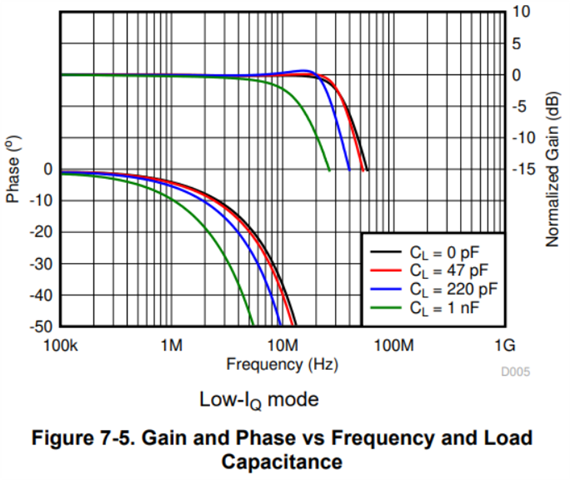
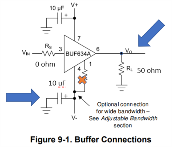
We've been looking over the datasheet for BUF634AIDDAR. It seems its bandwidth is 35 – 210 Mhz (which is above the audio frequencies). Also, found to places where the output impedance has been noted to be 5 ohm and 7 ohm. Can this buffer drive a 50 ohm load such as the SIM-43H+?

If not, can you suggest device for this application?

Thank you.

Regards,
Archie A.

  • Hi Archie,

    The bandwidth spec is from DC to 35 - 210MHz so it would work down in the audio frequencies. The driving capabilities of this device would depend on the signal being buffered as the concern would be output current considerations. The output impedance would cause a voltage divider with the 50-ohm load so that would be the consideration with this device as it does operate in an open loop. Regarding the application with the mixer, I am not too familiar with this application, but I am not sure if low frequencies would work with this mixer. One additional comment is that when driving complex loads such as a mixer, there is likely some kind of capacitance that would need to be considered. With most devices some kind of series resistance would need to be added to stabilize the circuit. This would also need to be considered as additional isolation series resistance would lead to additional voltage attenuation at the load. However, as mentioned depending on the output signal, this device could drive a 50-ohm load.

    Best Regards,

    Ignacio

  • Thank you, Ignacio, for your guidance.

    About this circuit:

    There is a capacitor with no label, is this the C_L capacitor which are listed in

    Also where is the Vo connection? This is not shown in Figure 9-1.

    I assume that I need to set it up as in Figure 9-1.

    73,
    Archie A.

  • Hi Archie,

    The capacitor you are referencing is a decoupling capacitor which is the same value as the one on the V+ node of 10uF. The C_L being referenced is the capacitive load tests that were ran for this device, which is tied directly at the output of the device. The Vo connection would be the output node and where you would tie your load or whatever you intend to drive with this device. Page 17 in the datasheet shows different circuit applications that this device could be used for. 

    Best Regards,

    Ignacio

  • Hello Ignacio,

    Thank you for your guidance.

    Should the decoupling capacitor for V- also be a solid tantalum 10-µF capacitor? Would it be correct to assume the following of Vo and V- capacitor (kindly see blue arrows).

    73,
    Archie A.

  • Hi Archie,

    I would reference the EVM schematic that is in the EVM users guide (attached below) for the best information on decoupling capacitors. We recommended larger decoupling capacitors (10uF) like the figure shows as well as additional decoupling capacitors closer to the supply pins that are in the 100nF range. The schematic will show this. But yes, the larger decoupling capacitors would be tantalum. Regarding your second question, could you explain what you mean regarding Vo and V- I am not sure I understand what you are asking.

    BUF634AD Evaluation module

    Best Regards,

    Ignacio

  • Hello Ignacio,

    So, the Vo in your docs look like this:

    While I changed it to this...

    Is this change correct?

    When you say:
    "Additional decoupling capacitors closer to the supply pins that are in the 100nF range."

    You mean at pin 7 and 4 closer to BUF634A?

    Thank you.

    73,
    Archie A.

  • Hi Archie,

    For the setup of Vo, this will ideally be connected to whatever is needed to be driven. The RL in the figure is arbitrary and can be 50ohms like you have. I would consider adding a placeholder for an isolation resistor incase you will be driving any capacitive load. Regarding your second question, yes that is correct. We usually have bulk decoupling capacitors closer to where your voltage supplies are on your PCB and we also add smaller valued decoupling capacitors closer to the device, so very close to pin 7 and 4. The EVM user's guide highlights both a schematic and layout which will show how we set up these decoupling capacitors. We also have a series resistor in our design which is what I recommended above.

    Best Regards,

    Ignacio

  • Hello Ignacio,

    Thank you for your guidance.

    Last question, do we have line driver configured to present exactly 50 Ω? Just to insure impedance matching between buffer and frequency mixer.

    73,
    Archie A.

  • Hi Archie,

    If the impedance looking into your load is 50-ohms, to impedance match you would want a 50ohm series resistance at the output of the buffer. If your load will be very close to the device output, you may not need to impedance match. However, as mentioned I would still add some kind of output series resistance as a placeholder in case your circuit needs some isolation resistance due to some capacitive load.

    Best Regards,

    Ignacio