Tool/software:
Hello
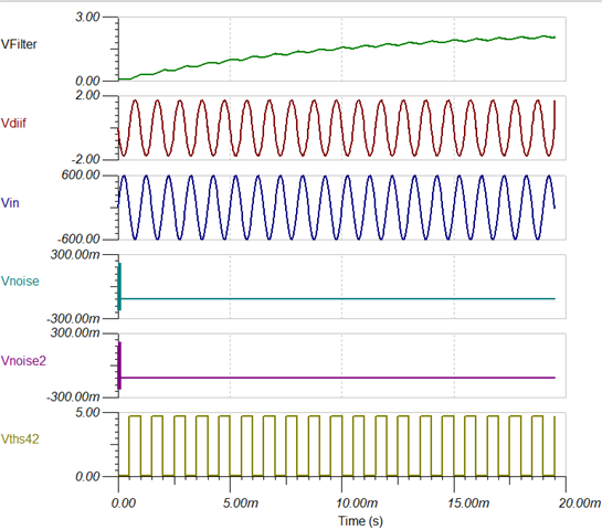
I am using THS4281 to determine if a part of my circuit is open-circuited or short-circuited. My main circuit is mainly high voltage AC, so I am using a voltage devider configuration along with a comprator structure, In Tina's simulation, for the short-circuited case, I expect to see 0V at the output of the opamp, and when there is an open-circuited situation, I expect to see alternating voltages at the output of the comparator. Vin is a Sin wave with 600V and 1khz frequency.
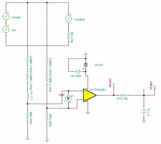
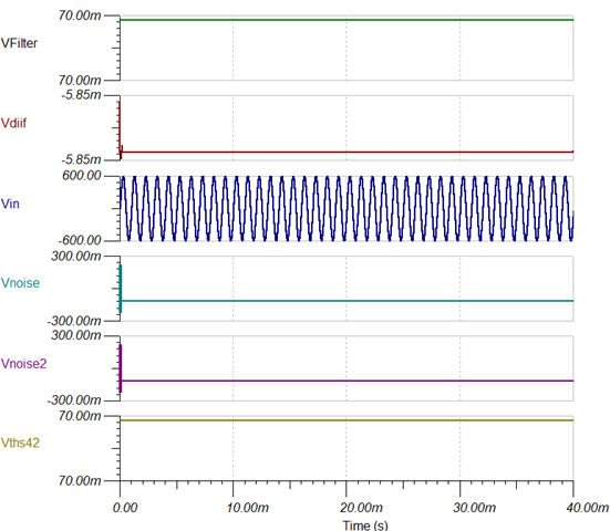
In the implementation, and for the short circuit condition, the output of the op-amp is VCC instead of being zero! I know that there are comparators available, and I already tried them in the simulation, and I still get the same response. I also know that op-amps and comparators in open-loop configurations are essentially unstable (the output is either 0 or VCC), and I was thinking maybe this causes the output of the op-amp in reality to go high instead of low. I attached the simulation results and was wondering if anyone could help me understand this.
Thank you very much
----------------------------------
Open circuit: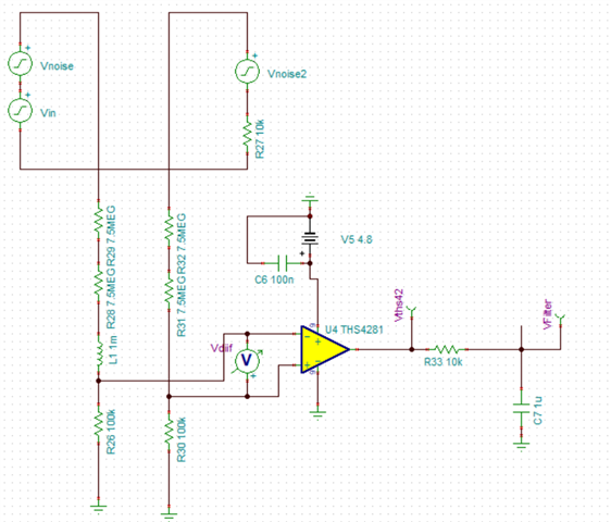
Short Circuit: