This thread has been locked.

If you have a related question, please click the "Ask a related question" button in the top right corner. The newly created question will be automatically linked to this question.

TLV3603: PSpice simulation issue

Part Number: TLV3603
Other Parts Discussed in Thread: PSPICE-FOR-TI

Tool/software:

Hi,

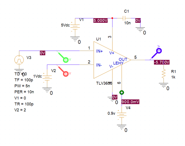
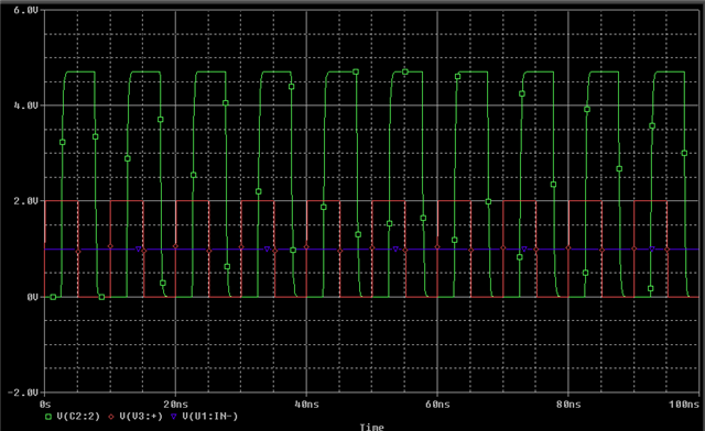
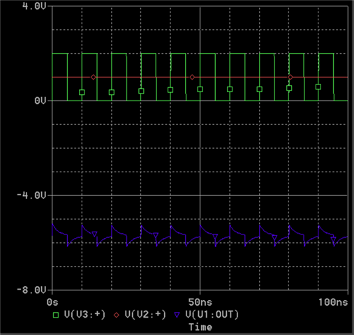
I downloaded PSpice for TI (v23.1-2024 S001) to try the TLV3603 model. I'm getting some strange negative voltages at the output pin. Can anyone help?

I've attached the design and some screenshots.

Kind regards,

Richard
  tlv3603_test-2025-08-12T10-56.zip

  • Hi Richard,

    I was able to get a correct simulation via the library in the TLV3603 product page:

    It's possible that there was a bug that was fixed in the product page version of the tlv3603.lib file that wasn't updated in the PSpice-for-TI version:

    Could you please download the model from the TLV3603 product page and add the tlv3603.lib from that zip and add it to your configuration files?

  • Adding the product page .lib file as shown didn't solve the problem, but I noticed the different pinouts in the diff you posted. Editing the pinout of the symbol fixed the problem.

    1. Right click on TLV3603 symbol
    2. Edit Part
    3. Change pin order to IN+ IN- LEHY OUT V+ V- 
    4. Change PSpiceTemplate to X^@REFDES %IN+ %IN- %LEHY %OUT %V+ %V- @MODEL