This thread has been locked.

If you have a related question, please click the "Ask a related question" button in the top right corner. The newly created question will be automatically linked to this question.

TLV6710: tlv6710

Part Number: TLV6710

Tool/software:

Hello,

We're trying to use the tlv6710 and are encountering some issues.
I've also read some forum discussions and I'm pointing out that the INA+ should not exceed 1.7 V.
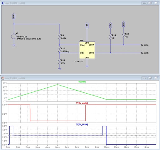
I downloaded the tlv6710 model and I notice that the OUTA voltage is 2.5 V when I expect it to be 0 V. I've attached the simulation.
Is this a normal behavior of the integrated circuit or a model issue?

Best regards,

  • Hello Christophe,

    It is the model. The model is designed to force the output to VCC/2 when ever the inputs are violated (either input >1.7V)

    The real device will NOT do this, but the output is not guaranteed when violating the input range on the real device.

    *****************************************************************************
    * Notes:
    * The following parameters are modeled: 
    * Iq, tpd, Ibias, Vcm, Vs, tr, tf, Vhys, UVLO, V(POR)
    * If either input or supply rail goes beyond the recommended max limits, the output will float at mid supply
    * If either input goes beyond the commmon mode limit, the output will float at mid supply
    * Modeled based off of typical EC table specs
    *****************************************************************************