


Other Parts Discussed in Thread: LM339
Tool/software:
Hello
I would like to design a circuit that detects if a fuse is blown or not in a 600V 60Hz AC system. In the picture below, F1_P and F1_S are two sides of a fuse, and I am measuring the voltage across them with respect to the signal ground of my circuit. As long as the fuse is fine, the LED turns on; if the fuse is blown, the LED turns off.
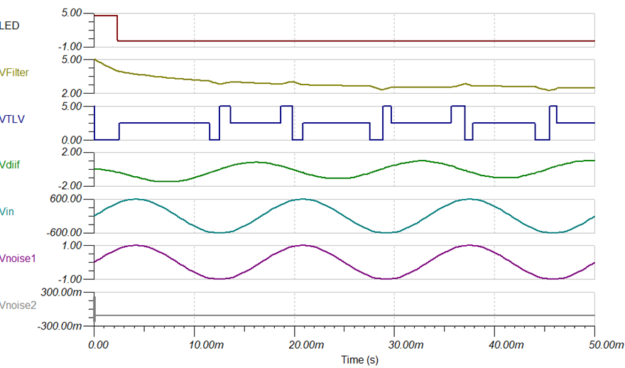
To elaborate further, I used an RC circuit in the output of the TLV to filter out the square wave caused by a blown fuse condition. So, after the filter, the output would be around 2.5V, then I have two other comparators with 1V and 4V levels. If the output of the low-pass RC filter is either 0V or 5V, it will turn on the LED; if not (fuse blown and Vfilter=2.5V), the LED turns off. I attached the simulation result using TINA
I would appreciate any help and comments regarding this design :-)

TINA simulation for when the fuse is OK:


TINA simulation for when the fuse is blown:


