OPA857: Not able to open simulation file

Part Number: OPA857
Other Parts Discussed in Thread: THS4541

Tool/software:

Hello,

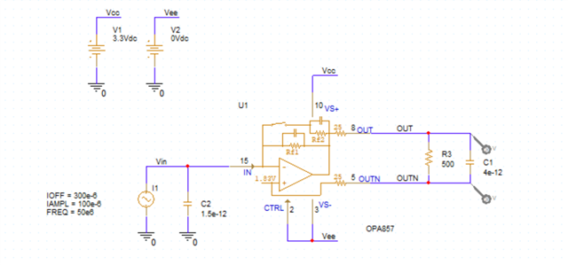
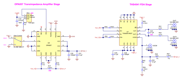
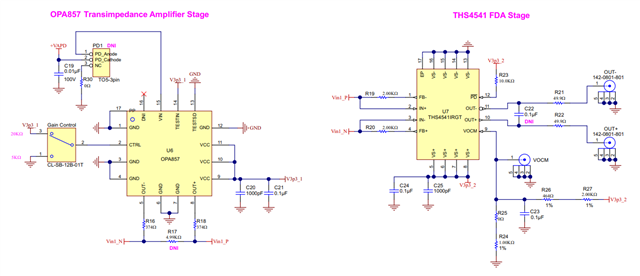
We are planning to use the OPA857 IC in our new design.

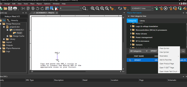
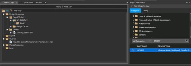
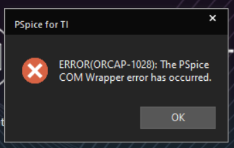
I have downloaded the OPA857 simulation file and tried to open it in PSpice for TI, but I got the following error.

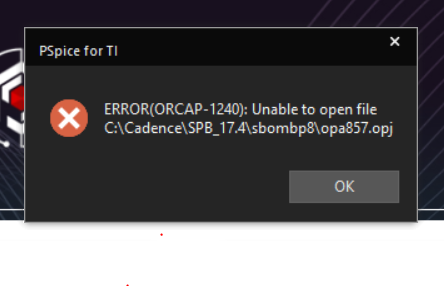
Could you please help to solve error?

  • Hello Hitesh,

      Would you be able to try this method:

    1. Open PSpice for TI
    2. Search OPA857
    3. Right Click on the OPA857 Part Name
    4. Click on Open Model Test Circuit
    5. Click on OPA857 PSpice Model

       Then, a new project will open:

      Open PAGE1*

      Let us know if above method works for you.

    Thank you,
    Sima

  • When create new project below error popup.

  • Hi Hitesh,

    I was able to get a document that goes through different debug steps that you can try. It seems like it is a system error not so much an error with our circuit file specifically.

    Best Regards,

    Ignacio

     COM Wrapper and Server Busy error.pdf

  • Hello,

    Run setup as administrator, then it works.

    We are planning to use OPA857 and THS4541 as per the image below.

    consider OPA857 gain to 5K.

    My question is: Our input current range is 50uA to 1000uA. In this condition, how much output will be on both IC output pins?

    Can I connect the THS4541 differential output (OUT- & OUT+) to STM32U585 ADC channels?

  • Hello Hitesh,

      I am glad it is working now, and thank you for sharing the fix.

      For your questions:

    1. Our input current range is 50uA to 1000uA. In this condition, how much output will be on both IC output pins?
      1. The output dynamic range of the OPA857 on a 3.3-V supply is 1.2 V. This 1.2-V swing corresponds to a maximum input current of 60 µA in the high-gain configuration, and 240 µA in the low-gain configuration. Therefore, I would recommend using the OPA857 in the low-gain configuration. However, the amplifier will start to saturate at 240uA and above which means your useable input current range is 50uA to 240uA. The output voltage at 50uA at low gain configuration will be 250mV and at 240uA it will be 1.2V.

      2. Output voltage will attenuate when adding a load, since there are internal series output 25ohm resistors. "With a 500-Ω differential load, the attenuation resulting from the load is 0.83 dB, which affects the overall transimpedance gain. Because of the load attenuation, the 20- kΩ transimpedance gain is reduced to an effective 18.2 kΩ, while the 5-kΩ internal resistor gain is reduced to an effective 4.5-kΩ internal resistor."

    2. Can I connect the THS4541 differential output (OUT- & OUT+) to STM32U585 ADC channels?
      1. Yes FDAs such as the THS4541 are optimized to drive differential input ADCs. 

    Thank you,
    Sima

  • Hello Sima,

    Thanks for the details.

    For OPA857, we can increase the input current range to 1mA using an external gain resistor.

    We performed two tests in simulation and obtained results as shown below:

    Test 1 - Gain: 5K, After 240uA, data does not change.

    Test 2 - Gain: 5K + 1.5K (External), Up to 1mA, we obtained results.

    Could you please check if the results are correct?

    We also observe there is no any change on OUTN pin.

    We also planning to connect THS4541 and provide input range as per Test result2.

    Connection and supply as per below image.

    Could you please tell me what value need to set for R16,R18,R19,R20 and VOCM voltage to get ADC count in STM32 MCU?

  • Hello Hitesh,

      Thank you for the updated details. Yes, your method and values are correct for the OPA857.

       For the THS4541 resistor and VOCM values, do you happen to know the ADC in STM32 MCU's full scale range and input common-mode voltage? The full scale range will determine the RF/RG values to meet the range of the ADC, and the input common-mode will determine what voltage the VOCM will need to be set to.

    Thank you,

    Sima