This thread has been locked.

If you have a related question, please click the "Ask a related question" button in the top right corner. The newly created question will be automatically linked to this question.

THP210: Connect THP210 diffrencial output with a long twisted pair cable to 12 Bits SAR ADC input

Part Number: THP210
Other Parts Discussed in Thread: OPA1637

Tool/software:

Hello,

I must connect the diffrential output of a THP210 op amp which has 30 mA output capability and enough bandwith over a long twisted pair cable AWG 22 to a 12 Bit SAR ADC inputs.

The application has the following parameters:

Amplifier Power supply : 3.3 VDC

Frequency range : 10 Hz to 20 KHz

Cable : Dual Twisted pair shielded AWG 22 ETFE, length may vary from 10 meter (30 FT) up to 100 meters (300 Ft)

I know that it's currently done with some audio sensors but my questions are the following :

- Do I have to teminate the line with something like a resistor or a transformer for adaptive impedance ?

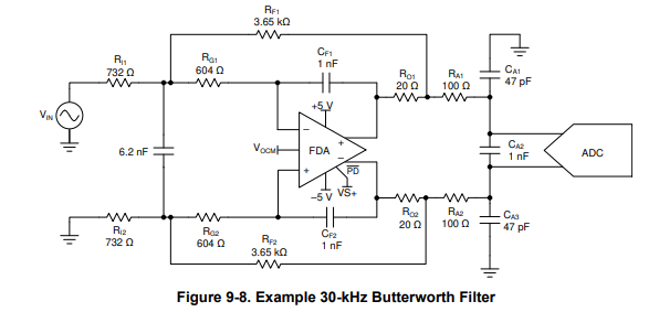
- Where to place the ADC input filters, close to the amplifier outputs or close to the ADC input side ?

- Is it the best method for this application ?

Thanks for,your advise.

Kind Regards,

Guy

  • Hello Guy,

    The key here would be how much bulk capacitance is seen differentially between the cables.  I am finding 22 gauge twisted pair capacitance values of 19 pF/ft as "low capacitance"; so, if I increase by 30 pf/ft, then I assume that would be conservative.  In that case, then we could be looking at 30 pF/ft*300 ft  = 9 nF, on the high side, and 0.9 nF on the low side.

    This device is effectively the same core device as the OPA1637.  In the OPA1637 data sheet, there is a graph that shows "Isolation Resistance vs. Load Capacitance" for a 40 degree phase margin:

    Since we could have anywhere from 0.9 to 9 nF, you should probably pick the maximum Riso value, around 70 Ohms.  This resistor must be outside of the loop, as shown in the schematic below as "RA1" and "RA2":

    For the ADC filter, I would also add additional R/C components in front of the ADC.  Some resistance is probably necessary to help protect the ADC from any excessive voltages forced on the inputs, and the capacitances would be chosen according to the ADC sample capacitance, which is dependent on the ADC.

    For a 12 bit SAR, the application is not too demanding, so you likely won't need to optimize the R/C filter at the input too much.  But if you know what your ADC parameters are, we also have an ADC drive calculator built into the Analog Engineer's Calculator tool.

    Let me know if this is helping you head in the right direction.

    Regards,
    Mike

  • Hello Mike,

    Clear and efficient reply, thank you!

    I never did this before and was looking for a solution.

    I plan to use PIC E10422 cable which has 42.7pf/m capacitance under 100 Ohms.

    So, I selected 69.8 Ohm resistors for RA1 & RA2.

    The SAR ADC has a 2us convertion time and a 2.5 uF sample capacitance. I'm surprise about the resistance and capacitance value given with your calculator : 51p and around 3K3 in the middle resistance value. Until now I used 1.5nF and 100 Ohm for direct coupling to the ADC on a pcb and worked fine...

    I will probably add a TPDE10B06DPYT surge diode on the connector pins to protect the ADC inputs.

    Thanks for your help.

    Warmly,

    Guy

  • Guy,

    The external filter capacitance (CF) that the calculator recommends is based on the internal sample-and-hold capacitance of the ADC.  CF is really a minimum value and using a larger CF will work even better at filtering the SAR transients.  The main downside to using the larger CF is that it will further limit the bandwidth, but sometimes that is desirable (i.e. better noise filtering).  So, your 1.5nF CF should work well and is fairly typical.  The ADC Precision Labs  section on SAR ADC Input Driver design covers the theory.

    I hope this helps!

    Best regards, Art

  • Art,

    Very interesting video's!

    Thank you !

    Best Regards,

    Guy