OPA547: OPA547F/500

Part Number: OPA547

Tool/software:

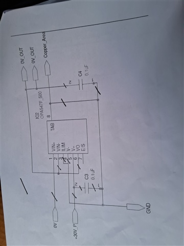
We are using OPA547F/500 power amplifier. The connection of the IC is as shown in figure. We are currently not using any heat sinks. When power supply is turned ON, the OPA547F amplifier is getting heated up and entering thermal shutdown mode. The current on power supply is shown as 280mA. This is happening in no load condition. How to resolve the issue?

  • Hey Akshay,

    Thanks for sharing your design with me. 

    I see a few problems:

    1. We need to make sure the device is being operated in a linear region. The amplifier is being configured in a unity gain buffer configuration with V- = 0V and V+ = 30V. Consequently, when we set IN+ to 0V, the amplifier tries to set Vout to 0V to minimize VID across IN+ and IN-. Due to the output swing limitations, the device cannot swing to the V- rail, and the device consumes more current trying harder to minimize VID.

    See table below for negative swing to rail performance:

    2. The load capacitor is far too large. A .1uF capacitor on the output will destabilize the device. Instability can often cause the amp to consume additional current and heat up due to high frequency oscillation inside the device. Even without a resistive load connected to the device, we can have significant issues with a heavy capacitive load connected to the device. 

    Here is a plot which shows the problem a bit more clear:

    Per this figure, even 4nF would likely be excessive to the amplifier. 100nF would certainly be unstable operation. 

    To retest this device, please input a voltage like 15V into the VIN node, and depopulate C4. 

    This should help solve the problem. 

    Please let me know what performance you see after these changes. We should see around 10mA Iq from the VCC rail in normal operation. 

    Thanks,

    Jacob

  • Hi Jacob,

    Your suggestion solved the issue. Thanks for your support.