This thread has been locked.

If you have a related question, please click the "Ask a related question" button in the top right corner. The newly created question will be automatically linked to this question.

INA333: Output is not linear

Part Number: INA333

Tool/software:
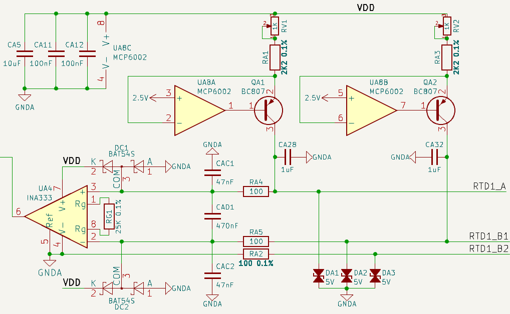
The circuit above shows a 3-wire RTD PT100 reader. I've measured the output current from pins A1-B2 and B1-B2 at 1mA each. VDD = 5V, GNDA = 0V.

I'm using a resistance generator to simulate an RTD. When the resistance is 100 ohms, the voltage measured between the Vin+ and Vin- pins is 0.098V, while the INA333 output pin measures 0.49V.

When I increase the resistance, for example, 200 ohms, the voltage measured between the Vin+ and Vin- pins is 0.197V, but the INA333 output pin measures 0.658V. Is there something wrong with my circuit?

  • Hello Khyarul,

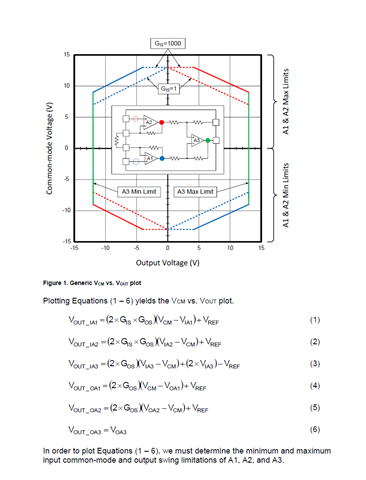
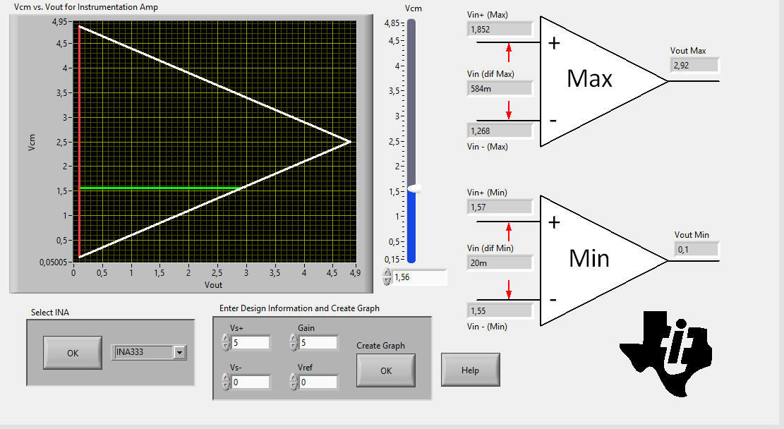
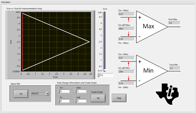
    What is the voltage referred to ground at each input? You may be running into the common-mode limitation of the device. If you would like to see what your valid output values are for a given input common-mode voltage, you may use the Analog Engineers Calculator: https://www.ti.com/tool/ANALOG-ENGINEER-CALC

    Best,
    Gerasimos

  • when the input is 100 ohms, the Vin+ voltage is 0.296V, the Vin- voltage is 0.197V. INA333 output is 0.49V

    when the input is 200 ohms, the Vin+ voltage is 0.395V, the Vin- voltage is 0.197V. INA333 output is 0.658V

    when the input is 300 ohms, the Vin+ voltage is 0.492V, the Vin- voltage is 0.197V. INA333 output is 0.822V

    All of these voltage measured is referred to ground (GNDA)

  • Hello Khyarul,

    Each of these input voltages correspond to a given common-mode voltage, and will have a corresponding output limitation. This limitation may be conservative, and could be somewhat exceeded in actual measurement, but when seeing this increased value, it should be understood that the internal amplifiers are not operating in their linear range, and you may see degraded performance at this output.

    Resistor IN+ IN- VCM Max theoretical output Ideal Output Value
    100 0.296 0.197 0.2465 0.293 0.495
    200 0.395 0.197 0.296 0.392 0.99
    300 0.492 0.197 0.3445 0.489 1.475

    To correct this, I would increase the value of RA2, Increasing the value of this resistor will increase your input common mode voltage. What range of input resistance are you expecting to measure?

    Best,
    Gerasimos

  • thank you, I get it now, could you also give me formula how to calculate the Max theoretical output value? (although I can get this value from the calculator)

    My resistance input value range is up to 400 ohms.

  • Hello Khyarul,

    The limitation is based upon the low level output swing limitation of the input amplifier A1. This is calculated based off of data that may not necessarily be available, as usually the output swing from rail of A2 and A1 are not usually published, and neither is the input CM range of the A3 amplifier. Some assumptions can be made to generate a reasonable estimate, though. The swing from rail of A3 is usually published, as well as the input CM range of A1 and A2. Assuming these are the same will allow you to calculate this value.

    For the range of inputs that you are looking for, and since ~2mA is going through RA2, increasing this to 750Ohm should ensure your inputs are within the common-mode voltage.

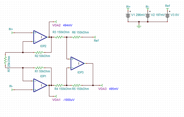
    Generally, this math is fairly complex, and it may be much easier to see the values with a simple SPICE circuit. For example, to generate the correct output with ideal amplifiers, the A1 amplifier would have to output -1mV

    Here is the circuit I used so you may test different conditions.

    INA333_Lin_op_check.TSC

    Best,
    Gerasimos

  • I decide to change the RA2 to 680 ohms (commonly used values), theoretically this will make Vin+ = 1.76V, Vin- = 1.36V, Vcm = 1.56V, ideal Vo = 2V when the resistance input = 400 ohms, I get the Vout max 2.92V, so I assume the Vo is within range, am I correct?

  • Khyarul,

    Yes, your understanding is correct, and is also confirmed with the linear operation checker simulation. All amplifier inputs/outputs will be in a linear operating range

    Best,
    Gerasimos