LM2902-Q1: Output abnormal

Part Number: LM2902-Q1
Other Parts Discussed in Thread: LM2902, , OPA4171-Q1, OPA202

Tool/software:

Hi team, 

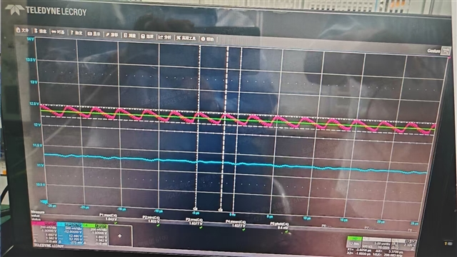
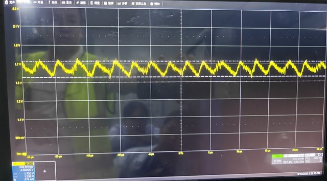
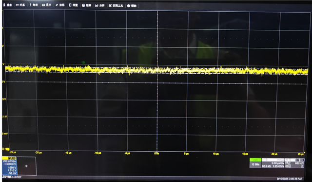
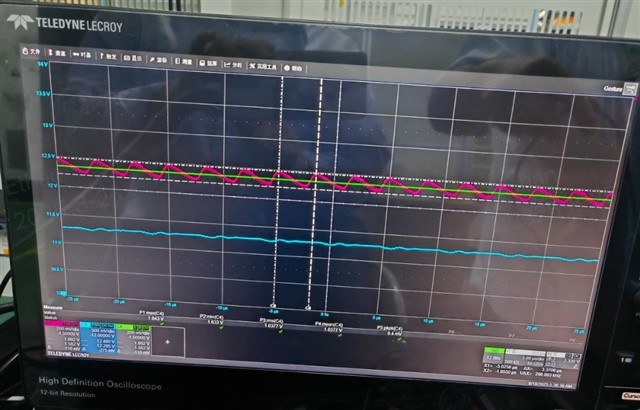
My customer is using LM2902-Q1 as a buffer for a 1.6V DC signal. But the output shows a sawtooth waveform when input is 1.6V DC. If they disconnect the DSP ADC input from this buffer, then LM2902 output is back to normal. You can find the waveform as below. 

Green one is input of LM2902-Q1, red one is output of LM2902-Q1. 

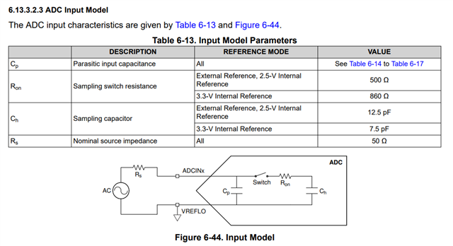
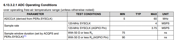
The DSP they are using is F280034-Q1, you can find the ADC information as below.

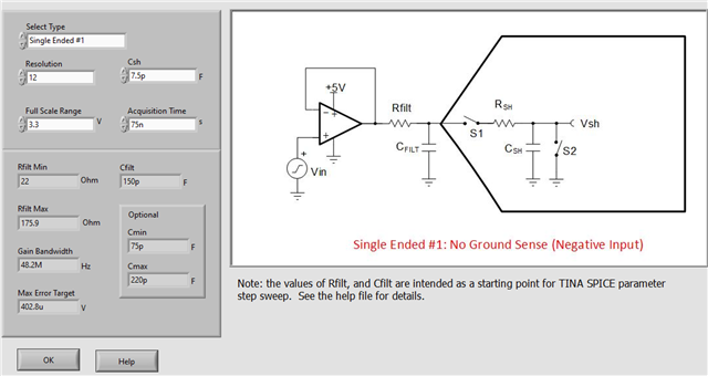
When I use analog engineer's calculator, I got below result. Customer original Rfilt=100ohm, Cfilt=1nf. From below result, it seems we should select a amplifier that bandwidth is about 50Mhz. But when customer change LM2902-Q1 to OPA4171-Q1, then output back to normal. 

So I would like to get your opinion on the reason on LM2902-Q1 output abnormal and how should we improve? 

Thanks!

Ethan Wen

  • Hi Ethan,

    I would like to get your opinion on the reason on LM2902-Q1 output abnormal and how should we improve? 

    Did you happen to use switching power supply in LM2902-Q1 op amp as buffer? What is the supply rail for LM2902-Q1, 5Vdc? Please check your ripple voltage and frequency components of 5Vdc with FFT. My guess is that the power rail for LM2902-Q1 (say 5Vdc) is noisy with high ripple voltage and high switching frequency. PSRR in LM2902-Q1 is unable to attenuate the high frequency components. The op amp buffer's output has approx. 300kHz frequency and +/-101mV ripple (barely able to read). My wild guess is that your supply rail has high ripple voltage greater than +/-200mV range and this is the root cause of the waveform at the op amp's buffer.  

    Please let me know if my guess is valid. You may need to use low ESR MLCC 10uF or large in order to attenuated the ripple voltage or filter out the high frequency components at the LM2902-Q1's supply rail (say use RC filter). 

    Best,

    Raymond

  • Hi Raymond, 

    The power supply they are using is 12V, which is from a switching regulator. But they don't observe a similar ripple on 12V. I am pushing customer to share a waveform on that. 

    Besides, since this sawtooth output will be disappeared when they disconnected DSP. Do you think it is still related to power supply? 

    Thanks!

    Ethan Wen

  • Hi  Ethan, 

    Besides, since this sawtooth output will be disappeared when they disconnected DSP. Do you think it is still related to power supply? 

    So the noise is related to DSP module. It is likely that the DSP's supply rail is not properly decoupled; PWM and related switching noises are likely coupled onto the 12Vdc. Or the DSP is taking more current when it is connected, and the switching power supply starts to generate higher spike amplitude and/or try to increase PWM frequencies to compensate for it (load issues at the switching power supply, please check for %load_regulation).  

    Please ask the customer to measure the 12Vdc with scope (not DMM), when the DSP is under a max. load in the system. Compare the 12Vdc rail's waveforms before and after DSP load is connected. My guess is that you will see a big difference in ripple amplitude and higher switching frequency components (verified with FFT spectrum). 

    My guess is that the LM2902-Q1's output noise is coupled via the noisy power rail, not the SAR ADC sampling frequency. 300kHz frequency is likely resulted from switching power supply and it is riding on top of 1.6Vdc (how is 1.6Vdc is generated? via voltage divider? see the image below). You can ask customer to insert 100Ω/1uF-10uF LPF filter next to the supply pin of LM2902-Q1 op amp ( in series with Vcc rail), and the issues are likely resolved. 

    LM2902-Q1 1p6Vref 08262025.TSC

    If you have other questions, please let us know. 

    Best,

    Raymond

  • Hi Raymond, 

    Here is the waveform from customer with V+(CH3, blue), input(CH4, green) and output(CH1, red). 

    We cannot see there have ripple on 12Vdc power supply. The other phenomenon I want to point out is that the output will be back to normal if they change Rfilt from 100R to 220R or increase 1nF Cfilt. 

    Do you think it is related to the capacitive load or SAR ADC drive circuit design? 

    Tomorrow I will go on-site for debug, please let me know any suggestions. 

    Thanks!

    Ethan Wen

  • Hi Ethan,

    The output stage of the LM2902-Q1 is a bit different than other amplifiers, and I suspect this issue might be related. 

    When you are doing debug onsite, you could try connecting a pull up or pull down resistor in parallel with the Cfilt to see if the oscillations improve. See the crossover distortion section of Application Design Guidelines for LM324 and LM358

    Best Regards,

    Alex Curtis

  • Hi Alex, 

    Thanks for your suggestions. We tried three things today. 

    • Decrease Cfilt from 1nF to 47pF, Rfilt keep 100ohm. The Vpp of oscillation increased from 110mV to 176mV. You can find the waveform as below. 
    • Connected a 10kohm pull down resistor in parallel with Cfilt=1nF, Rfilt=100ohm. Then the oscillation improves much. We almost cannot see the 300kHz oscillation. You can find the waveform as below. 
    • Keep Cfilt=1nF and Rfilt=100ohm, remove 10kohm pull down resistor, replace LM2902-Q1 with SGM8240-4(2.2Mhz GBW) and OPA4171-Q1(3Mhz GBW). Then the oscillation was gone. 

    Questions: 

    1. What is root cause for this oscillation? 
    2. According to the "Analog Engineer Calculator" result, this SAR ADC drive amplifier bandwidth should be >48Mhz. Is it because of GBW? How can we verify it? I am thinking if you can help recommend a 10Mhz GBW amplifier, but other parameters are similar with LM2902. Then I can evaluate if it is caused by GBW. Can you recommend one? They are using TSSOP-14 package. 

      Thanks!

      Thanks!

      Ethan Wen

  • Hi Ethan,

    I'm glad to hear the 10k load resistor helped.

    The OPA4171-Q1 you tested has a higher GBW (3 MHz) and faster slew rate (1.5 V/us) compared to the LM2902-Q1, which make it better at driving a SAR ADC. As mentioned earlier, the output stage of the LM2902-Q1 has some limitations compared to other amplifiers, so my theory is the output stage of the amplifier is creating the distortion. Regardless, using a higher GBW part would be a good idea.

    As the note under the schematic diagram indicates, the calculator result is meant as just a starting point, so for more details on selecting the filter component values as well as criteria for selecting the buffer amplifier, I would recommend reviewing our TIPL content below:

    https://training.ti.com/ti-precision-labs-adcs-introduction-sar-adc-front-end-component-selection?context=1139747-1140267-1128375-1139106-1128643

    As well as this older presentation that has some additional details: /cfs-file/__key/communityserver-discussions-components-files/14/4478.PA_2D00_001--Optimize_5F00_SAR_5F00_converter_5F00_design-REV-b.pdf

    Best,

    Alex Curtis

  • Hi Alex, 

    As mentioned earlier, the output stage of the LM2902-Q1 has some limitations compared to other amplifiers, so my theory is the output stage of the amplifier is creating the distortion.

    To prove this, can you recommend one P2P amplifier which has same GBW with LM2902-Q1 but different output stage? I can put into customer system to verify. 

    Thanks!

    Ethan Wen

  • Hi Ethan,

    I have a suggestion for this; the OPA202.  The OPA202 has a really solid output stage with low output impedance (50 Ohm) for its current consumption, and is 1 MHz bandwidth.  The issue though is the input common-mode range only goes to 1.5 V from the negative rail.  The circuit you have shown above is set at 1.6 V, so it should be OK, but they won't be able to go below 1.5 V.

    Can you check on that one and let us know what you think?

    Regards,
    Mike

  • Hi Mike, 

    Ok, thanks! 

    I will apply OPA202 samples for them. If we verify OPA202 is no problem, then the root cause of this issue is output stage of LM2902-Q1. 

    Thanks!

    Ethan Wen

  • Hi Ethan,

    Ok, let me know how it goes.

    Regards,
    Mike