Tool/software:
Hi team,
I have a customer currently looking at using the BUF802 clamping circuitry and running into some issues. Do you have a more precise diagram or explanation of how the input and output clamping circuit works?
-------
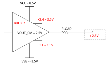
The current circuit I have implemented is identical to the evaluation board composite loop however since we want to have the output of the BUF802 sit at 2.5V, I am applying -2.5V as shown in the diagram:

Now I want to set my output clamps to clamp at 3.5V and 1.5V (+/- 1V away from the 2.5V CM). When I set the CLH to 3.3V it seems to clamp at 3.5V like I want it to, however I cannot get the CLL to work at all, I would expect that I just set the voltage at CLL to somewhere around 1.5V to get it to clamp there but I'm finding out that it doesn't work, I actually have to push the CLL voltage way higher, like in the 3V range to start seeing any clamping. My rails are set to -4V to 9V so that my mid supply is at 2.5V. So the voltage at CLL is actually passed the max input spec of the datasheet which said not to go higher than mid supply. Any idea on what I'm doing wrong?
Best regards,
Randy