Other Parts Discussed in Thread: XTR300, XTR200, XTR111
Tool/software:
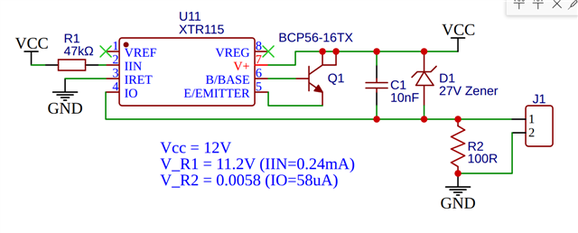
I have this circuit using an XTR115 and using R2 to test the current output. As you can see from the text in the schematic, the output current is only 58 microamps instead of 24mA. I am pretty much at my wits' end here. Do you see anything wrong with the circuit as shown? Or the testing of it? I figure I am missing something obvious but cannot see what.
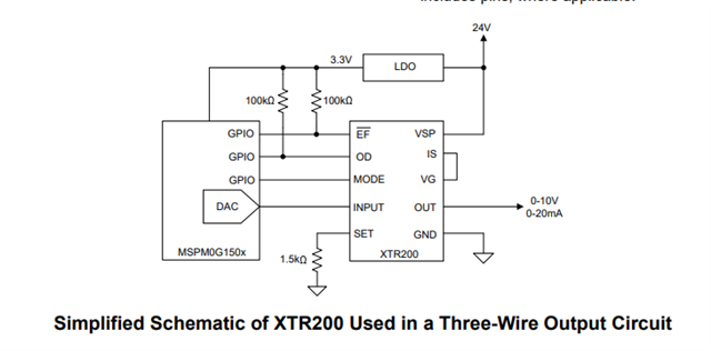
Also, after watching the TI video Introduction to 4-20-mA current loop transmitters, I realize that I should possibly be using a 3-wire solution (I am providing output current from a PLC). However, neither the video nor the data sheet for the xtr300 make a lot of sense to me in how it is connected to an output device - e.g. the transmitter ground and device ground are shown as different (not connected?). Also, is there a reason the XTR115 chip cannot be used as I am attempting in this application (I am supplying VCC)?
The world of current transmitters is new to me, and I would like as simple of a solution as possible for my application.
Thanks for any help.