Tool/software:
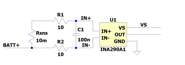
I am planning to use INA290-Q1 /A1 Device) as current sensor
In some cases there will be 40V at IN+ and IN-, but no voltage at Vs, the voltage difference between IN+ and IN- (Vsense across sense resistor) will be 0V
If I look at figure 6-15 in the data sheet, I would have assumed the input bias current into IN+ and In- would be close to 0uA
But in Spice simulation and in real life, the bias current into IN+ and In- is approx. 39uA each
Please clarify how I miss read the datasheet