OPA357: OPA357

Part Number: OPA357
Other Parts Discussed in Thread: LMH13000

Tool/software:

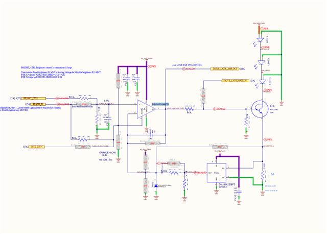
I am trying to design a LED current controlled pulsed circuit (the pulse duration  is 4.6us and the current need to be limited to 5A during the pulse duration 

Does Ti have any mosfet driver solution with current limiter in a single package which uses some high speed op-amps and sense the current and drive the gate to limit the current on  the DS path 

  • Hello Agxin,

      We have newly released the LMH13000 which is an integrated voltage-controlled current driver for laser diodes that can support continuous current of 50mA to 1A and pulsed current of 50mA to 5A. This will have the output FET integrated within the device. Will this work for your application, or still would prefer a discrete solution.

    Thank you,
    Sima

  • Thanks for the response . 

    the supply voltage required is 24-28V

    the Led is connected to anode  using this supply and the cathode is connected to the driver ,

    I am  looking for a low side current sense control  high side sense control is also ok if its supporting higher voltage I am trying to minimize this circuit 

  • Hello Agxin,

      Sorry for the delay, I wanted to confirm with our systems engineer for the device if it will work in above configuration.

      The LMH13000 will work in this type of application and can use VSET pin on the device as the control which will work similarly to how it is done in a discrete solution with FET in a closed-loop system for current control. This way it will be confined in one integrated chip solution. 

    Thank you,

    Sima

  • Can you share the voltage drop across the led. 
    may I ask how critical is to keep the supply at24V is it being driven by the sum of 3 voltage drops across the led ? 

  • That will require a huge supply capable of providing 5A*16 @15V min  voltage drop across LED 4.7*3

    we are using higher voltage to store the energy in the cap and discharge the energy stored in CAP to the strips  the charging power available is less but the peak power for the LED is higher 

  • so the drop across LED = 4.7 * 3 = 14.1V , 
    As you can see the minimum headroom required by LMH13000 to act as a current sink when 5A is flowing though it is ~ 1.6V. ( refer to Figure 5-27 in datasheet).
    This means that voltage node 28_VDD_Flash ideally has to be 14.1V + 1.6V = 15.7V.
    Also i have noted your point on the voltage across the cap droops due to the output power from the caps being more than the input caps.

    I have 2 solutions here for you : 

    Solution 1 : 

    The maximum voltage which LMH13000 can handle is 18V, so we can allow a droop of 18V - 15.7V = 2.3V. Since I = C * ΔV/ΔT. If i plug I = 5A, ΔV = 2.3V and ΔT = 4.6us , the C comes out to be : 10uF. Which is small enough . a 10uF if charged to 18V , will not dip below 15.7V which is what is required during the entire duration of 4.3us even if there is no additional charge given to it.

    Solution 2 : 

    You use the fixed bias current option available in LMH13000 to keep a fixed current through the LED all the time. This will allow a certain voltage drop across the LED even during the off stage. You can keep the fixed DC bias current through the LED very low to ensure minimal optical output. This will allow you to bias the LED bias voltage higher since in this case LMH13000 IOUT pin will not see more than 18V.