THS4631: heats up quite a lot

Part Number: THS4631

Tool/software:

Hello everyone,


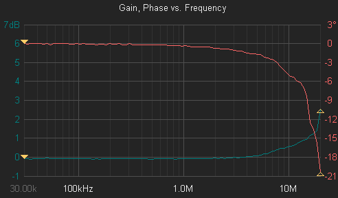
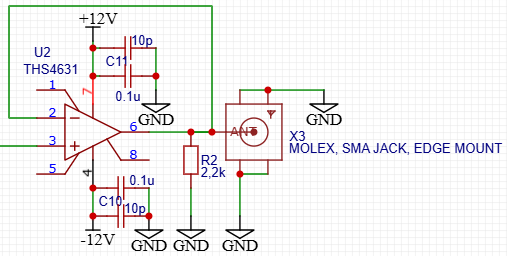
I’m bringing this topic up again because I still can’t solve the problem of this circuit overheating. I chose this IC to build a buffer (voltage follower) with a gain of 1 V/V, in order to match the impedance of the measuring system. I assembled a classic voltage follower circuit. I tested the characteristics and, from what I can see, everything seems to work as it should — except for one thing: the package gets extremely hot.

I’ve already redesigned the PCB twice; in the latest configuration I even flipped the IC and soldered a heatsink directly to its tab to ensure the best possible heat dissipation. But even in this setup, the heatsink temperature reaches 86 °C. Is such a temperature normal for this IC?

The supply is bipolar ±12 V, and during tests I apply a sine wave with 1 V amplitude at the input. As a load I currently use a 2.2 kΩ resistor, but I’ve also tried values from 50 Ω to 1 MΩ, and it doesn’t solve the problem.

  • Hi Yevhen,

    This should not be happening with this device as it should function well in unity gain. Does the device have any stability issues when measuring at the output? Does the device heat up even when no input signal is applied?  

    Best Regards,

    Ignacio

  • If there is no signal at the amplifier input, its temperature is significantly lower. Heat can still be felt, but there are no issues with excessive heating. This can also be seen in the thermal image attached to the question. It shows two identical amplifier paths. The one with the higher temperature has a 1 V amplitude signal connected to its input and is noticeably hotter, while the other has no input signal and remains cooler.

  • Hi Yevhen,

    When there is no signal at the output can you probe the amplifier to see if there is any oscillation. Could you also share how you are measuring this signal? What is connected to your SMA output? 

    Best Regards,

    Ignacio

  • The amplifier was tested using a KEYSIGHT DSOX4154A (with FRA option), connected as shown in the attached screenshot.

    With the input terminal grounded and no input signal applied, the output shows only noise with an amplitude of about 10 mV, which is close to the oscilloscope’s resolution.

    However, when the input terminal is left floating, the output noise amplitude increases to about 1 V.

  • Should I connect the input terminal to ground through a high-impedance resistor, like 1 MΩ?

  • The DC component was also measured. With the input left floating, the amplifier output exhibits a significant DC offset of approximately 7 Vdc, given a bipolar power supply of ±12 V

  • Hi Yevhen, 

    For testing the device, grounding the device with a 0-ohm resistor would work. This much resistance at the input could cause some offset issues, so a 0-ohm resistor would be better. Floating the input would cause issues as the device would not be biased correctly. Could you share an image of your PCB.

    Best Regards,

    Ignacio