INA217: Digital potentiometer for gain adjustment, distortion

Part Number: INA217
Other Parts Discussed in Thread: TPL0202-10, PGA849,

Tool/software:

Hi

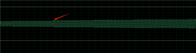
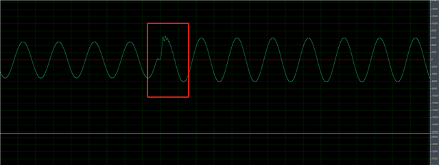
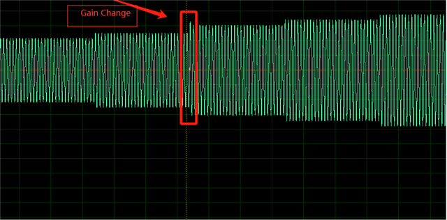
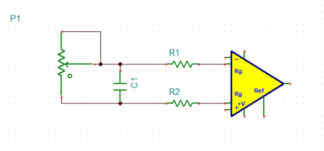
   Customer feedback shows that when using a digital potentiometer to adjust gain, there may be signal distortion at the moment of resistance change. Suspected to be caused by discontinuous changes in the resistance of the digital potentiometer. Is there any solution.
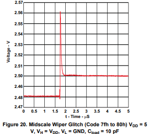
distortion waveform

  • customer use TPL0202-10 as digital potentiometer

  • Hi Kai,

    Do you know if the customer has a specific set of gain values they wish to use for their application? If so, I would recommend a programmable gain amplifier given that we have a product with the supporting gain options they require. However, there will still be some signal distortion between changes in gain by using a programmable gain amplifier due to switch capacitance, as shown below with the PGA849. 

    If the customer wishes to use a potentiometer, then I would suggest adding some filter to smooth out the distortion seen when adjusting the potentiometer. Are they using the potentiometer in the same configuration as the application diagram you provided?

    Could the customer provide a schematic of their design? Also, do you know the frequency of the plots provided?

    Best Regards,

    Taylor Allan

  • Hi,

      Customer use INA217 as Microphone preamplifier, they need use  potentiometer to set gain. the test signal frequency is 1Khz, SCH as below.

    Please help to advise how to filter distortion, thanks!

  • Hi Kai,

    Thanks for the schematic. It looks like there is some glitch happening on the RG pin that is causing this issue. In this case I would use an implementation like the one below. It does require some fine tuning to make sure that the glitch is removed and the device stays stable.


    I would still recommend the customer use a PGA if possible, especially since they are having to, but ultimately I understand if it is a hard design requirement. Below shows how a PGA849 can be used as a mic preamp.

    Best Regards,

    Taylor Allan

  • Hi,

       What should be the value of capacitor C1 set.

  • Hi Kai,

    Here is a little bit of context of why I suggested this design. Essentially, adjusting the potentiometer injects a fast AC signal into the input of one of the buffer amplifiers, which is a differential signal that is seen in the waveform the customer provided (as shown below).

    Adding a capacitor turns this differential signal into a common mode signal, which would eliminate the output distortion. The problem with this solution is that adding capacitance to the inverting inputs of the buffer amplifiers can cause stability issues, which can be eliminated by adding isolation resistors R1 and R2. The customer can watch our op amp training series, which addresses stability here. Adding these resistors of course will increase the resistance seen between the RG pins which limits the gain of the INA.

    It is difficult to provide specific capacitor (for C1) and resistor values (for R1 and R2) as you cannot directly measure the bandwidth/Aol/Zo of the buffer amplifiers, which is important for knowing the location to place the zero.

    I would suggest the customer does the following:

    Start with Riso values of 100ohms and a capacitor of 100pF, and increase the value of the capacitor until the glitch is removed. Then, test the stability of the system by inputting a small step response on the IN+ pin of the INA, and measure the output. Depending on the overshoot seen in the output, use the Analog Engineer's Calculator to determine the phase margin. If the output is unstable, then adjust the Riso values until the system is stable

    Best Regards,

    Taylor Allan