


Tool/software:
Hi All,
I am using INA199A1 to sense current from current transformer. I am attaching the schematic snapshot. I am getting non-linear output . Please suggest what am I doing wrong.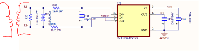
Original question:

Tool/software:
Hi All,
I am using INA199A1 to sense current from current transformer. I am attaching the schematic snapshot. I am getting non-linear output . Please suggest what am I doing wrong.

