OPA192: sine-wave-amplifier-to-drive-inductive-load-at-a-constant-current

Other Parts Discussed in Thread: OPA192

Tool/software:

Dear Sir/Madam,

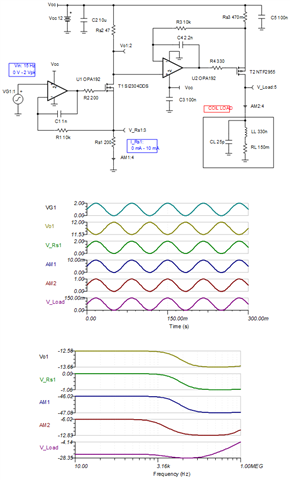
I saw the following post:

Sine wave amplifier to drive inductive load at a constant current - Amplifiers forum - Amplifiers - TI E2E support forums

I am interested in this solution and if it is possible to drive the coil without the DC offset.
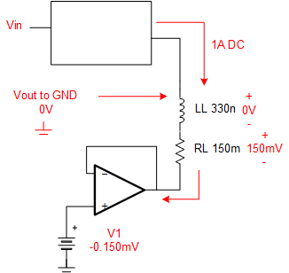
Similar specification 15Hz to 60Hz into 33uH inductor with 0.15Ohm DCR.
Single supply having maximum of 5V or 12V.

Regards Joe

  • Joe,

    You found a very good post to solve your issue.  Since your inductance and series resistance is less than the original design, you can use this circuit without modification.  I adjusted the power supply and your load but that is is.  I am not sure what you mean by drive the coil without DC offset.  The coil will develop a DC voltage according to your current and the coil resistance (0.15 ohm in your case).  The op amps themselves do have a DC offset but it is in the microvolts.  With Vin = 0V, this circuit outputs approximately 0A.  There will be a slight offset current due to the input offset of the op amps but that is in the microvolts and OPA192 is among the best op amps for offset voltage.  The DC transfer function, AC transfer function, and transient response are shown below.  Attached is the TINA source file.


    OPA2192_different load.TSC

    Best regards, Art

  • Hi Art,
    Thank you for the reply.
    The 33uH inductor will have very low impedance at 15Hz, 3.1mR and will dominate the DCR of 150mR.
    From your simulation the output is 150mV. Is it possible to increase in the range of 2 to 5V?

    Regards Joe

  • Joe,

    The input sine wave has a DC offset of 1V and 1Vpk amplitude, so the maximum voltage is 1V + 1Vpk = 2V.  The transfer function is Iout = Vin*(500mA/V).  Thus the output current peak is Iout = 2V * 500mA/V = 1000mA.  The output voltage will be approximately 1000mA * 150mΩ = 0.15V.  The only way to reduce this voltage is to: 1) reduce the output current, 2) reduce the DCR of the coil.  I doubt that you can decrease the resistance but maybe the current gain is higher than you want / need.

    When you say, "it possible to increase in the range of 2 to 5V", I think that you are asking for a 0V to 5V signal.  Below is the simulation.

    You can download TINA-TI for free and try experiments yourself.  It is actually pretty easy to use and intuitive.  To adjust the input signal you just click on the signal source.  I hope this helps.  Let me know if you have additional questions.

    Best regards, Art

  • Hi Art,

    Thank you again for the reply.
    Sorry, for not being clear.

    VG1 would still be 0 to 2V from a DAC.
    V_Load would be 0 to 5V. After testing a fixed value of 0 to 2V might be used. It would be good to have the flexibility.

    Regards Joe

  • Joe,

    V_Load is currently 0.15V max when the maximum voltage of 2V is applied.  Are you saying you want to increase the load voltage from 0.15V to 5V?  I don't think I am understanding you correctly.  This is a voltage to current source.  You can adjust the current gain by adjusting Rs3 (Rs3 = 470mΩ now).  Decreasing Rs3 will cause current gain to increase.  Since your circuit is an inductor the output voltage will depend on frequency.  As you mentioned at the low frequency of the simulation the XL is negligible companied to the DCR of the coil.  Thus, for the frequency we are currently operating at the inductor really doesn't change the output and the output is only from Vo = I*DCR.

    You might want to download TINA and run some experiments, and/or spend some extra time putting together a more detailed explanation of what your goals are. 

    Best regards, Art

  • Hi Art,
    Thank you.

    Regards Joe

  • Hi Art,
    Would it be possible to take this offline so I can share some additional details?

    Regards Joe

  • Joe,

    Sure.  Send me a friend request, and I will give you my email via a private message.

    Art

  • Hi Art,

    What I am trying to implement is a voltage controlled current source similar to what is described in this thread except 0V centered. ie. no DC offset.

    Regards Joe

  • Joe,

    FYI.  I did not receive a friend request, and this is on a public form.  The problem with your diagram is that it does not show the coil resistance (DCR).  You cannot avoid a voltage drop across that resistance.  If your goal is to make sure that the voltage to ground is 0V than you can make the output referenced to a small DC voltage to cancel the offset.  Since your input signal is changing in the actual circuit, the canceling signal would probably need to be related to Vin.  Is your goal to cancel the offset due to DCR to ground?  I really think this should be resolved in a call.  Send me a friend request and we can discuss over the phone.

    best regards, Art

  • Hi Art,

    I did send a request. I have two options now send private message and cancel friend request. I sent you a private message now.
    The inductor values and DCR have not changed since the original post (33uH and 150mR). The voltage and current waveforms are 15Hz.  
    I hope you get my message so I can share more details.

    Regards Joe