This thread has been locked.

If you have a related question, please click the "Ask a related question" button in the top right corner. The newly created question will be automatically linked to this question.

LMV7219: Low or abnormal output level

Part Number: LMV7219
Other Parts Discussed in Thread: TLV3511, TLV1872

Tool/software:

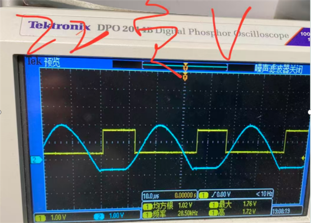
Test conditions: The input signal is a 28Khz sine wave, and the output is a square wave,Another adverse phenomenon is that the phase and signal amplitude are both normal, but the signal will suddenly be pulled low and then return to high level when it is high.
Adverse phenomenon: The output level amplitude is significantly low and the phase is offset.
Defective rate: 12.5%, 16/128PCS
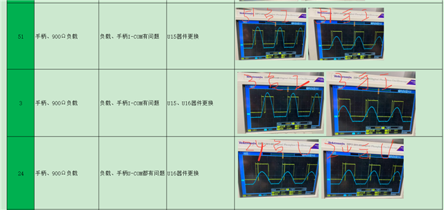
Replacing with new materials is likely to solve the problem, but there is still a probability of the same issue occurring.
Could experts please take a look at the reasons behind this?

  • Hello Huangjian

    1. The input to the LMV7219 cannot be driven negative (below ground). The op-amp output looks to be being diode-clamped to GND.

    2. The LMV7219 is not a rail-to-rail input and has an input limit of VCC-1.2V, or 3.3V - 1.2V = +2.1V maximum input voltage.

    The valid comparator input range is -0.1V to +2.1V. Applying signals outside of this range can cause false outputs.

    The detail in the scope photos is poor, so I cannot see if the "glitch" is occurring at ~2V. But "glitches" or "reversals" are a common sign of violating the input range.

    In any case, this is not the correct way to zero cross detect. The output of the op-amp is being hard-clamped to ground on the negative swing (increasing the op-amp power dissipation..is the op-amp warm?).

    The output of the op-amp needs to be level-shifted into the 0 to 2V range. No existing comparator can accept a large (-5V) negative voltage.

    At absolute minimum, there should be a 10k resistor between the op-amp and comparator input to limit the negative swing current and an external diode clamp. The TLV3511 could be used to accept the input voltage up to +5V.

    Another option is to use the TLV1872, which has separate input and output supplies and is designed specifically for applications like this and eliminates the need for level shifting.

    In your case:

    VCCI = +5V

    VEEO = -5V

    VCCO = +3.3V

    VEEO = GND

    In this configuration, the input can accept a full +5 to -5V input signal, and the output will swing 0 to 3.3V.

    Similar to this (but at ±5V input):