LMH6611: Schematic Check & Do we really need Electrolytic Capacitor at power supply if application is not audio amplifier

Part Number: LMH6611

Tool/software:

Hello TI Support Team,

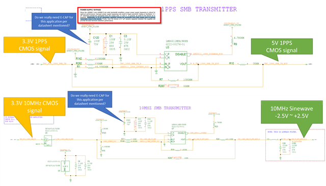
I am using the LMH6611 in my design and have a question regarding the power supply bypassing recommendations.

My application involves conditioning a 1PPS 5V CMOS and a 10MHz sine wave -2.5V~2.5V signal.

The datasheet's "POWER SUPPLY BYPASS" section on page 23 recommends using a 10 µF electrolytic capacitor.

Since my application is not for audio, could you clarify if this 10 µF electrolytic capacitor is still critical for stability and performance?

We are trying to save board space and would prefer to use an MLCC to replace E-capacitor solution if possible.

Perhaps i can enable 47uF with higher voltage rating MLCC to replace 10 µF electrolytic capacitor.

I have attached our schematic for your review. Thank you for your assistance.

  • Hello Alfred,

      Thank you for the details and reaching out! Yes, you can continue with just the two ceramic capacitors (0.1µF and 10µF) and ignore the 10 µF electrolytic capacitor. At the time of device release and datasheet creation, ceramic capacitors were not as common at these higher values. They do help with removing low-frequency ripples for very noise power supplies, but this shouldn't be a concern especially as you mentioned in sensitive audio applications. Even in later cases, adding a ceramic capacitor + low resistor will do the same job. You can read a bit more if interested here: ceramic capacitors replace tantalum capacitors.

       And as you have seen from the section, but will add it here as a note: The 0.1µF ceramic capacitor should be close to the supply pin of the amplifier and the ceramic 10µF can be closer to your supply source. We usually as X7R capacitors. Also, make sure to choose MLCCs that are at least rated to 2x to 3x of the highest applied voltage. 

    Thank you,

    Sima

  • Hi Sima,

    Thanks so much.