This thread has been locked.

If you have a related question, please click the "Ask a related question" button in the top right corner. The newly created question will be automatically linked to this question.

TAS5805M: EMI suppression

Part Number: TAS5805M


Tool/software:

Hi BU,

My customer is having some issues with EMI. 

Can my customer replace the inductor with a 10uH choke coil?

Or can only add the choke coil like this?

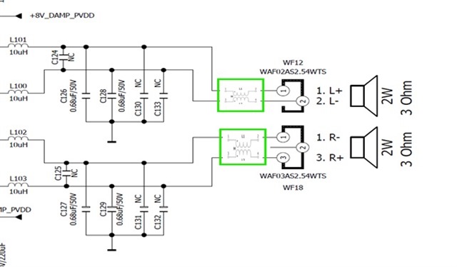
Besides that, do you recommend ferrite bead when it comes to EMI suppression? If yes, what are the changes to be made? 

Thank you!

Regards,

John

  • Hi John, 

    Yes the inductors can be replaced with the choke coil. I am not sure what would happen if the choke coil is placed after LC filter... This is not the typical use. 

    If the LC filter is not solving the EMI issues the customer can try ferrite beads. See below for typical ferrite bead filter rec from datasheet. 

    Regards,
    Sydney Northcutt

  • Hi Sydney, 

    Thank you for your comments!

    Regarding the values of LC filter circuit, primarily L101, L100, L102, L103, C126, C128, C127 and C129, are these values correct? Any values are inappropriate and need to change? 

    Regards,

    John

  • Hi Sydney, 

    Good day to you!

    My customer is doing EMI scan with a probe on the PCB, it was found out that there is a highest emission at around 768kHz as shown in the image below. 

    Questions:

    • Is 768kHz ring a bell on some switching frequencies?
    • Any ways to reduce the emission at this 768kHz? 

    Thank you!

    Regards,

    John

  • Hi John, 

    The customer will need to add some filter to suppress the amplitude of this harmonic. Also, is the class-d switching at 384 or 768 kHz? This may just be the class-d switching.

    Regards,
    Sydney Northcutt