This thread has been locked.

If you have a related question, please click the "Ask a related question" button in the top right corner. The newly created question will be automatically linked to this question.

LM675:Short-circuit fault between Vcc and VEE

Part Number: LM675


Tool/software:

Dear Technical Support Team,

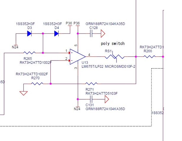
We are currently using the LM675T/LF02 on one of our boards.
Recently, we encountered a failure in which the supply  (Vcc to −VEE) became shorted within the LM675T/LF02.

Our initial assumption is that through-current may have occurred between the high-side and low-side transistors in the output stage.

However, while investigating the cause of failure in the driver section, we have not been able to identify any external factors that might have triggered the issue.

For reference, the supply voltages in our application are +33 V and −24 V.

Could you kindly advise what potential causes may lead to such a failure in the LM675T/LF02? Any guidance on possible mechanisms or conditions that could result in this type of short circuit would be greatly appreciated.

Sincerely,

  • Hello Yamamoto-san,

    Your thinking is typically correct, shorts between VCC and VEE typically occur due to output stage damage creating a low resistance path to form. 

    The most common way we can see this damage occur is through Electrical Overstress (EOS).

    This can appear as the output being forced to a potential or excessive current flow which causes damage to the output stage. 

    In the case of power amplifiers, we have a similar EOS type requirement being the SOA curve. The device will often try to maintain operation within the SOA curve, but large transients or reactive loading effects can cause the amplifier to exit safe operating area for enough time to cause damage. Generally when driving reactive loads, we recommend placing external current steering diodes to help prevent EOS events. 

    What is the LM675 connected to? Is this the only unit which has failed?

    +33V and -24V is perfectly valid for the operation of the device. 

    If you have a curve tracer, you could look at the output stage transistors relative to the supply rail. I would imagine these will be shorted like you mention. 

    Do you have a schematic I could look at? 

    Thanks,

    Jacob

  • Hello Mr. Jacob Nogaj,

    A polyswitch has been placed at the output to provide a current limit of 100 mA.
    In addition, although there are ten identical circuits using the LM675, only this particular IC has failed.

    Please find attached the surrounding circuit of the LM675 for your reference.

    Please let us know if you also require the surrounding amplifier circuitry.

    Sincerely,

  • Hello Yamamoto-san,

    This is interesting to see. I like to see the polyswitch, this should offer some protection. The diodes on IN+ are also welcome.

    What value is R266? Is there any chance of a power sequencing being incorrect? 

    I do not see any apparent issues in the schematic. 

    Is ESD any risk in this design?

    Thanks,

    Jacob 

  • Hello Mr. Jacob Nogaj,

    Thank you very much for your response.

    The value of R266 is 10 Ω.
    We believe there are no issues with the power-up sequence.
    However, when the LM675 failed, the chip fuses located on the +33 V and −24 V supply lines were found to be blown. It is possible that these fuses may have opened prior to the failure of the LM675.

    There is no risk of ESD in this environment.

    We would greatly appreciate your further review and confirmation.

    Sincerely,

  • Yamamoto-san,

    Thank you for the details here. R266 should help limit current in fault state. 

    I am unsure what caused failure here. Perhaps the chip fuses were blown, and then the amplifier had load current continue to pull from the output, causing over-voltage damage. 

    Where does the supply power come from? Is this LDO powered? Were the fuses common to all of the power amplifiers, or just used for this one power amplifier?

    Good to know that ESD is not a concern here.

    Thanks,

    Jacob

  • Hello Jacob,

    Thank you very much for your response.

    I can understand that the failure could be explained by the fuse blowing and the amplifier continuing to source load current from the output, leading to over-voltage damage.

    That said, since the other nine circuits are supplied from the same power source and have not failed, we are also considering whether there might be other contributing factors. The power is supplied directly from an AC-DC converter to the board and then distributed through fuses to the nine power amplifiers.

    As these units are being used at a customer site, we do not know exactly how they were operated, so it may simply be that this one device happened to fail under those conditions.

    Nevertheless, we are concerned about the possibility of the same issue occurring again in the future.

    Sincerely,

  • Thank you for the additional information.

    I am still uncertain how we could have issue, but I would imagine the most likely situation is a fault appearing only on this amplifier. 

    Please keep us in the loop if you see any future issue with this device. We are happy to offer support.

    I can always support a curve trace analysis of the damaged part to better identify the damaged circuitry inside the device. 

    Thanks,

    Jacob

  • Hello Jacob,

    Thank you.
    For now, I’ll wait and see how things go.

    Sincerely,