XTR115: RS232 to current loop conversion

Part Number: XTR115

Tool/software:

Hello, I have been tasked with creating an RS232 to current loop converter in order to communicate with a PLC.

I have never made electronic boards before and I admit that I am having a little trouble understanding how the connection works.

I am not starting from scratch, as I have the electronic diagram for the converter that is currently in use.

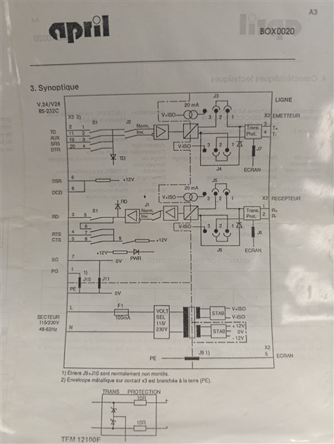
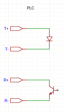
Data reception and transmission are managed in this way in the PLC :

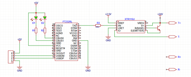
For now, I have accomplished this, but I know there is still a lot of work to be done.

Has anyone ever done this type of connection and could help me finish the circuit diagram?

  • Hi Antoine,

    Thanks for using E2E, I'm glad to help! Firstly, I would recommend you look watch our short training series on 4-20mA transmitters linked here, so that you can get a better understanding of their requirements and use cases if this is your first time designing with them.

    I haven't seen this use case before, as normally a 4-20mA transmitter is used for transmitting analog signals not digital. I can point you towards a couple E2E threads that you can use here to help you with your design:

    [FAQ] What is a 2-wire 4-20mA current transmitter?

    [FAQ] Are there reference designs that can help me build a 4-20mA transmitter?

    Here are some quick comments/questions about your current design:

    Since the XTR115 is a 2-wire transmitter, the Iret pin must be kept floating, which is why it is necessary to use an isolator between the FT232RL and the XTR115. Here is a link to our digital isolator portfolio. Also, for a 2-wire system, the 24V supply has to be in the loop itself. Below is an example circuit that uses the ISO7310 to isolate the Iret pin from the GND of an MCU, as well as a correct supply voltage configuration:

    Am I correct in that the output of the XTR115 connects to a PLC input diode? The output of a 4-20mA is almost always connected to a resistive load, where the voltage across it can be measured by an ADC. If there is a resistive load, another thing to keep in mind is the compliance voltage of the XTR115. With a compliance voltage rating of 7.5V, the maximum resistive load in the output loop is (24V-7.5V)/(20mA) = 825Ohms.

    Do you know if you can use a 3-wire transmitter instead? If so, it might be better for your design since it seems like the transmitter has access to a power supply.

    Best Regards,

    Taylor Allan