Tool/software:
Hello,
this is a follow-up question to this posting.
An NTC is usually connected to an Op Amp or single-ended ADC through a voltage divider:

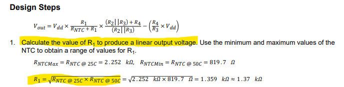
In both cases, the resistor R1 of the voltage divider can be chosen in order to optimize the linearity of the output for a given temperature range TMIN to TMAX. The formula is given in the datasheets and uses the respective NTC resistances RMIN (at temperature TMIN) and RMAX (at temperature TMAX):
R1 = sqrt( RMIN * RMAX)
I wonder how to derive at this formula? The original posting does not answer this question or rather I don't understand the answer.
The original posting refers to a formula of the NTC resistor as below:
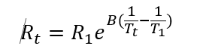
It is not explained, why R1 in this formula should be the same as R1 in the circuit.
As you know, the formula of the NTC resistance usually includes a certain resistance Rx and temperature Tx where the NTC is calibrated to, e.g., Rx=10k at Tx=25°C, and a BETA value. These three values are usually provided in the specification by the manufacturer. So the general NTC resistance formula is:
RNTC(T) = Rx * exp(BETA(1/T-1/Tx)
I lack to see why the calibration resistance Rx inevitably corresponds to the resistance R1 of the voltage divider.
However, I know that I can calculate a (geometrical) mean temperature Tm for the range TMIN to TMAX respecting the reciprocal nature of the temperature in the NTC resistance formula:
1/Tm = 1/2 (1/TMIN + 1/TMAX) => Tm = 2* TMIN*TMAX/(TMIN+TMAX)
To calculate the corresponding mean NTC resistance Rm, I use this NTC resistance formula with the specifics for the NTC factored out into constant C:
RNTC(T) = C * exp(BETA/T) with the constant C including the specification of the NTC: C = Rx * exp(-BETA/Tx)
Inserting Tm gives: Rm = RNTC(Tm) = C*exp(1/2 * BETA * (1/TMIN + 1/TMAX))
= C* sqrt(exp(BETA/TMIN)) * sqrt(exp(BETA/TMAX))
= sqrt( C * exp(BETA/TMIN)) * sqrt( C * exp(BETA/TMAX))
= sqrt (RMIN * RMAX)
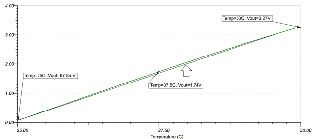
So I understand how the mean resistance Rm is calculated but I don't see why the linearity is improved by setting the resistor of the voltage divider R1 to Rm.
Can you please help?
Thanks.
Daniel